P

You are using an out of date browser. It may not display this or other websites correctly.
You should upgrade or use an alternative browser.
You should upgrade or use an alternative browser.
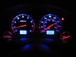
I see BLUE!!!!
- Thread starter rookie
- Start date
GiggityGiggity
Member
- Location
- Toronto Canada
looking real good rookie!
<jealous sniker>
")
<jealous sniker>
shralp
Member
- Location
- San Diego, CA
I see blue .... and purple

I blew the circuit board in the process so i ended up wiring the LEDs directly to 12v. The red needle LEDs still work and they blend into the blue a little. I should have added a few more LEDs for the fuel and oil gauges but i'm satisfied.
I blew the circuit board in the process so i ended up wiring the LEDs directly to 12v. The red needle LEDs still work and they blend into the blue a little. I should have added a few more LEDs for the fuel and oil gauges but i'm satisfied.
Attachments
- Location
- Westminster OC
- Car
- car
I believe he put a flexible led strip around the perimeter of the cluster to light the lower areas and kill off the red.
You is a brave brave fxers.
You is a brave brave fxers.
- Location
- Santa Clarita, CA
- Car
- 2005 FX45
That is a great effort! Kudos!
- Location
- FONTANA, CA
- Car
- 2010 Honda Crosstour
Wow, very nice. Looks good. Much better than orange.
raymond
Member
- Location
- Netherlands
- Car
- FX35 RWD
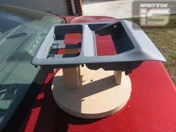
Got the cluster back, and relocated my oem display up top like I've been meaning to do foever!
Here's the maplight housing Competition Soundworks modified for me. Pre-paint, it's painted DG to go with the headliner.

Rookie, do you know what the guys from Competition Soundworks will charge to make your overhead like that...?? As i'm planning on doing that for a whil as well.
Thing is there is a panel sold in japan but it's quite expensive i think
P.s: great job on the leds also...!! Any updates on those costs as well...??
Attachments
hey shralp, what kind of lights were behind the shift indicator and odometer? i thought that those were a sealed unit where you had to change the screen, etc. on those.
i got all of my bulbs on order/received minus the leds. i may just order a lot of 0805's and 0603's and say screw it. i don't wanna wait any gahdam longer to do this mod....
i got all of my bulbs on order/received minus the leds. i may just order a lot of 0805's and 0603's and say screw it. i don't wanna wait any gahdam longer to do this mod....
Yeah man I wish I could get one of those also. I don't like relocating my screen down below where the clock used to be...Rookie, do you know what the guys from Competition Soundworks will charge to make your overhead like that...?? As i'm planning on doing that for a whil as well.
Thing is there is a panel sold in japan but it's quite expensive i think
- Location
- Westminster OC
- Car
- car
Moving that display up there is not for the faint of heart. The control board is connected to the screen by a flat ribbon cable, it is only so long so the control board has to go up there as well.
I had to hack the connector off and extend I think it was 15 or 18 wires up to the headliner. With the control board flipped I soldered to the backside of the connector which was basically straight to the pcb.
I had to hack the connector off and extend I think it was 15 or 18 wires up to the headliner. With the control board flipped I soldered to the backside of the connector which was basically straight to the pcb.
raymond
Member
- Location
- Netherlands
- Car
- FX35 RWD
Moving that display up there is not for the faint of heart. The control board is connected to the screen by a flat ribbon cable, it is only so long so the control board has to go up there as well.
I had to hack the connector off and extend I think it was 15 or 18 wires up to the headliner. With the control board flipped I soldered to the backside of the connector which was basically straight to the pcb.
Yes i understand that it's not going to be an easy job,but it should be dooble when you have somebody with you who understand wiring i think and we have seen it on both forum before done by others.
So that still holds te question: How much...??
By the way: Does anybody already have sort of a list needed to do this LED Conversion: Amounts / Types / Wich type > Wich Location / etc....
Yep, I knew about the ribbon cable... extending it would be no problem for me. It would take me tops half an hour to get all wires extended and the connector back on several feet of wire later.The control board is connected to the screen by a flat ribbon cable, it is only so long so the control board has to go up there as well.
raymond
Member
- Location
- Netherlands
- Car
- FX35 RWD
Yeah man I wish I could get one of those also. I don't like relocating my screen down below where the clock used to be...
Haha Cube,your the same as me i gues, always " IMPATIENTLY WAITING..."
By the way: Does anybody already have sort of a list needed to do this LED Conversion: Amounts / Types / Wich type > Wich Location / etc....
i have some leds ordered that are for the switches/clock/etc. once i get in there, i'll post a list for everyone of what goes where once i tear into this.
raymond
Member
- Location
- Netherlands
- Car
- FX35 RWD
Any news concerning wich leds to order. As i'm planning on taking a look at this mod in the winter time,but would like to order the parts first before taking it all appart.
shralp
Member
- Location
- San Diego, CA
The LEDs behind the climate control are PLCC-4. I had a hard time finding them so i never got that far.
The gauges are lit up by 2 bulbs. They're twist lock's but I'm not sure what size they are. I tried the wrong ones and blew the circuit board.
The LEDs behind the LCD displays next to the gauges are PLCC-4's. There's 4 of these, 2 behind each LCD screen.
Each gauge needle has 1 PLCC-2 LED.
The high beem indicator and blinkers are twist lock bulbs but I don't know what size.
The AWD, VDC, and all those other indicator lights are PLCC-2.
Behind the stereo buttons are reaaaaally small LEDs. I forget what size i tried but they were too big. There's about 60 of these.
The lights in the window switches are PLCC-2.
Hope this helps!
- Location
- Southern California
I have done the LED conversion on a Accord before and had to rebuild the "bulb"
there is a write up here
http://www.ledautomotive.com/HowToGuides/98-02Accord/DashLEDHowToAuto.asp
Now pull the bulb out of the plastic holder and insert the LED through the holes.[/FONT]
Note which side is the anode and which side is the cathode. Unlike regular bulbs, LED's are polarized and will not work if you plug them in the wrong way. The anode is the + lead and is longer than the other. [/FONT]
 [FONT=Arial, Helvetica, sans-serif]
Bend the negative (-) lead so it goes into the groove. Bend the positive (+) lead 90° from the other groove and cut both leads so that they do not stick out past the bulb holder. It will help if you can bend the positive (+) lead slightly toward the end. (See right picture.) [/FONT]
Solder[/FONT][FONT=Arial, Helvetica, sans-serif] one end of the wire (included with your kit) to the the negative (-) lead and wrap the wire around the bulb holder in the groove. The wire will go where the contact leads on the stock bulb were before you removed the bulb. Cut off any extra wire an put the end of the wire in the groove. [/FONT]
Take another piece of wire (included with your kit) and bend it in a "U" shape an put it on the bulb holder as shown in the left picture. Cut one of the ends short enough so it will fit down in the groove, and bend the wire into the groove. Next cut the other end of the wire and fold it into the same groove. It is OK if it overlaps the other end of the wire as seen in the picture on the right. [/FONT]
The left pictures shows what it should look like. Place a resistor (included in your kit) between the LED lead and the wire you just wrapped around the bulb holder and solder both sides of the resistor. [/FONT]
Here is a diagram that shows the layout of an LED correctly installed.[/FONT]
[/FONT][FONT=Arial, Helvetica, sans-serif]*Important!* - While soldering, do not hold the soldering iron to the LED lead, resistor or the solder joint for more than 3 or 4 seconds. If the solder does not make a good contact, wait until it cools before heating it up again. If you hold the soldering iron on the solder joint too long, the resistor and/or the LED will become useless. The resistor will go out before the LED will, we have included extra resistors in case you need them.[/FONT]
[FONT=Arial, Helvetica, sans-serif]
A trick to help you solder the tiny resistors on the bulb holder is to use your pliers to hold the bulb holder. Put a rubber band around the handle so it holds the bulb holder and use your tweezers to hold the resistor into place with one hand while you solder it with the other hand.[/FONT]
there is a write up here
http://www.ledautomotive.com/HowToGuides/98-02Accord/DashLEDHowToAuto.asp
[FONT=Arial, Helvetica, sans-serif] Bulb To LED Conversion [/FONT]
[FONT=Arial, Helvetica, sans-serif] Now we need to take all of our bulbs and convert them. Remove the stock bulb from the base by unwinding the two contact leads. You might need a used staple or something to pick the leads up from the grooves.[/FONT]
[FONT=Arial, Helvetica, sans-serif]
 [/FONT]
[FONT=Arial, Helvetica, sans-serif]
Now pull the bulb out of the plastic holder and insert the LED through the holes.[/FONT]
[FONT=Arial, Helvetica, sans-serif]
 [/FONT]
[FONT=Arial, Helvetica, sans-serif]
Note which side is the anode and which side is the cathode. Unlike regular bulbs, LED's are polarized and will not work if you plug them in the wrong way. The anode is the + lead and is longer than the other. [/FONT]
Bend the negative (-) lead so it goes into the groove. Bend the positive (+) lead 90° from the other groove and cut both leads so that they do not stick out past the bulb holder. It will help if you can bend the positive (+) lead slightly toward the end. (See right picture.) [/FONT]
[FONT=Arial, Helvetica, sans-serif]

 [/FONT]
[FONT=Arial, Helvetica, sans-serif]
Solder[/FONT][FONT=Arial, Helvetica, sans-serif] one end of the wire (included with your kit) to the the negative (-) lead and wrap the wire around the bulb holder in the groove. The wire will go where the contact leads on the stock bulb were before you removed the bulb. Cut off any extra wire an put the end of the wire in the groove. [/FONT]
[FONT=Arial, Helvetica, sans-serif]
 [/FONT][FONT=Arial, Helvetica, sans-serif]
 [/FONT][FONT=Arial, Helvetica, sans-serif]
 [/FONT]
[FONT=Arial, Helvetica, sans-serif]
Take another piece of wire (included with your kit) and bend it in a "U" shape an put it on the bulb holder as shown in the left picture. Cut one of the ends short enough so it will fit down in the groove, and bend the wire into the groove. Next cut the other end of the wire and fold it into the same groove. It is OK if it overlaps the other end of the wire as seen in the picture on the right. [/FONT]
[FONT=Arial, Helvetica, sans-serif]

 [/FONT][FONT=Arial, Helvetica, sans-serif]
 [/FONT]
[FONT=Arial, Helvetica, sans-serif]
The left pictures shows what it should look like. Place a resistor (included in your kit) between the LED lead and the wire you just wrapped around the bulb holder and solder both sides of the resistor. [/FONT]
[FONT=Arial, Helvetica, sans-serif]

 [/FONT]
[FONT=Arial, Helvetica, sans-serif]
Here is a diagram that shows the layout of an LED correctly installed.[/FONT]
[FONT=Arial, Helvetica, sans-serif]
 [/FONT]
[FONT=Arial, Helvetica, sans-serif]
[/FONT][FONT=Arial, Helvetica, sans-serif]*Important!* - While soldering, do not hold the soldering iron to the LED lead, resistor or the solder joint for more than 3 or 4 seconds. If the solder does not make a good contact, wait until it cools before heating it up again. If you hold the soldering iron on the solder joint too long, the resistor and/or the LED will become useless. The resistor will go out before the LED will, we have included extra resistors in case you need them.[/FONT]
[FONT=Arial, Helvetica, sans-serif]
A trick to help you solder the tiny resistors on the bulb holder is to use your pliers to hold the bulb holder. Put a rubber band around the handle so it holds the bulb holder and use your tweezers to hold the resistor into place with one hand while you solder it with the other hand.[/FONT]
[FONT=Arial, Helvetica, sans-serif]

[/FONT]
[/FONT]
[FONT=Arial, Helvetica, sans-serif]Not sure if the Fx uses the same bulb holder, but at least gives you some ideas hopefully.[/FONT]
[FONT=Arial, Helvetica, sans-serif] [/FONT]
[FONT=Arial, Helvetica, sans-serif] [/FONT]
Last edited:
shralp
Member
- Location
- San Diego, CA
Those are some helpful pics. The twist lock bulbs in the FX are similiar from what i remember but i don't know if it's possible to take the bulb out like that. I blew the circuit because i replaced it with the wrong bulb!:thumpdown:
A little more info i have .... the LEDs behind the stereo buttons are SMDs (service mount diodes) and i think i counted about 60. I think i tried a 1206-SMD but it was too big. I think the best way to figure out which ones are needed is by measuring them with a really accurate caliper. Then shopping for them based on their size.
I gave up on this whole thing ... for now
Share: