onthemove MOD's

What do you have?
Huh?

Just wondering cause it's got it's own box that wraps around the cone and it uses the air funneled in by the OEM pieces... It can be used with other tubes, like the LMS tube instead of the z-tube (which I had before and it kinda sucked)...
 
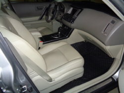
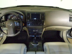
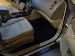
Got the SCOTABC mats yesterday and glad I did. Here's the review FX35 - SCOTABC FLOOR MATS
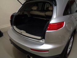
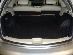
Still waiting on the cargo mat. I think they make these for Z's and G's but if they don't, they might if you ask them to. Gonna put the dash cover in the trash. Frankly, I'd rather look at a few small cracks until I get to the final solution. Even if they made these in a color that perfectly matched one of the 2 colors in this interior, I think I'd still go with black.
DSC01122.JPG DSC01123.JPG DSC01124.JPG DSC01125.JPG
 
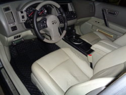
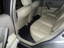
I spent just a little time heating and shaping a few areas to help the mats settle into their new home and took some better photos as well without the flash. Trashed the dash cover. These things fit like a glove and I like'em more now than I did when I first installed them yesterday. Also tucked the mats underneath the center console on the driver and passenger side as opposed to finding a solution to the one area that needed a fastener on the driver side. I think these can be tucked in anywhere there's an adjacent panel which I might do later on, not that there's a reason, but I do like to tuck!
The cargo mats need a little work, primarily adding some velcro to the tops of the mats that attach to the rear sets but other than that, not too shabby, especially considering I paid $0.
DSC01142.JPG DSC01144.JPG DSC01145.JPG
DSC01146.JPG DSC01147.JPG DSC01148.JPG
DSC01201.JPG DSC01200.JPG DSC01194.JPG
 
Last edited:
I know! They make the FX look and feel a little more elegant inside, not that that's what I was going for, but I like it. I just wish I didn't waste my time cleaning the carpets a couple months back. Oh well. There's mats very similar to these made for the Porsche Macon that sell for $330 iirc.
 
Last edited:
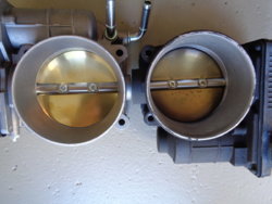
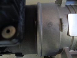
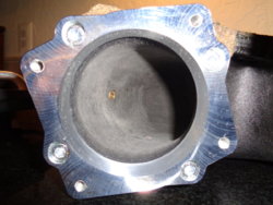
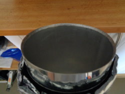
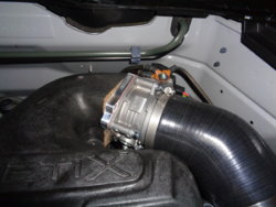
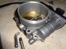
Got a 75mm throttle body & doing some other intake mods. Photo 1 shows the old and new side by side and photo 5 shows the face of the old fits into the mouth of the new. The silicone coupler for the intake pipe is a pita to get on now, but I have a fix for that which will also allow the opening to hug the silicone coupler, decreasing turbulence.
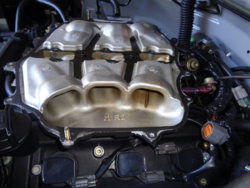
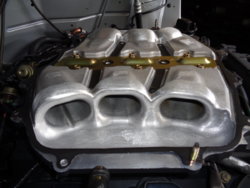
Pulled the v-plenum and noticed the mishimoto catch can is slacking a bit. I didn't expect it to catch everything. This engine never had an oil consumption issue, thankfully, but after installing the v-plenum for the first time, I thought it would be a good idea. Now, I'm not so sure. Nissan, as many if not all other manufacturers may have wanted, even counted on some oil getting on the piston rings topside. Tight tolerances might be a reason or it could just be a minor drawback from the pcv system. The increase in compression from the oil that so many seem to be worried about is probably only a concern if FI, high compression or when a large shot of n20 is in play. This increase in compression reminds me of a "wet" compression test, except under normal operating conditions, it's always wet, assuring good compression and possibly less wear on the walls?
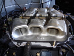
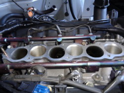
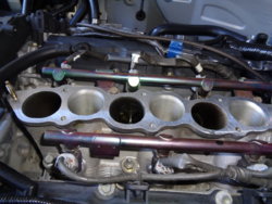
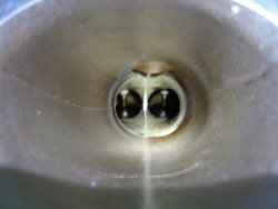
The discoloration in the intake manifold concerned me awhile back. I didn't notice that all 6 are coated until I took these photos. Initially, I thought it was just the 3 heading to the passenger side cylinder head. The long side of each runner is clean while the short side is coated. When looking straight down into the combustion chamber, it looks clean all around. 94k miles.
DSC01167.JPG DSC01170.JPG DSC01172.JPG DSC01171.JPG DSC01169.JPG DSC01173.JPG DSC01174.JPG DSC01176.JPG
 
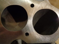
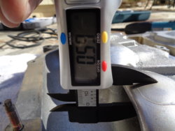
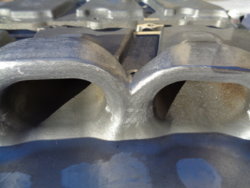
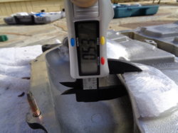
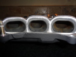
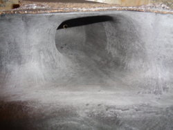
Part of this mod is opening up the lower collector runners where they mate to the intake manifold. Originally, I planned on matching but I don't have the time nor the interest in taking it that far. The intake manifold's runners are "stepped", in other words, they're larger all around than the runners from the lower collector.
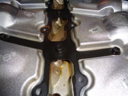
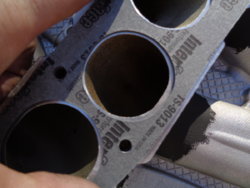
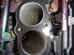
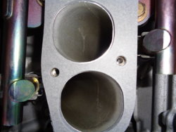
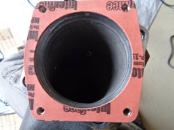
Photo's 2 and 4 show the Aramid iso-thermal spacer placed on the intake manifold. Photo's 3 and 6 show the stock gasket. Notice how they both shift to the driver side. The Aramid fits much better. Even though it doesn't line up perfectly, none of the Aramid is overlapping any runner opening (it's close though) while the stock gasket overlaps every single runner and always on the left side as facing. That's pretty fuckin sloppy work Nissan.
Photo 1 shows the Aramid on the lower collector. Great fit. I used the stock gasket as a guide, keeping in mind that they both have a shift to the right when installed on the manifold, and taped it down. I used a 1/2 round file and removed approx. 2mm on each runner then followed that up with sand paper, finally 1200 grit. No porting, just opened up the rough casting, photo 5.
DSC01179.JPG DSC01178.JPG DSC01223.JPG DSC01222.JPG DSC01242.JPG DSC01224.JPG
DSC01272.JPG
 
Last edited:
Another part of this intake mod was to mrev2 my lower collector. This is good for 3-4 hp/tq per Tony at MD as well as a few other independent dyno charts, none of which I was able to copy and paste. Damn photobucket. I took 6mm off the tops of the front 2 runners but I also returned them back to their original shape as opposed to just chopping the top as most, including MD do. Will that make a difference? Beats the shit out of me but with the minor nuances made to the mrev2 and after spending a little time studying what Nissan was trying to do with this design, I don't think it hurt.
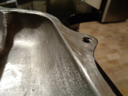
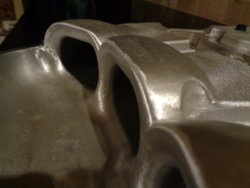
Nissan took the time to 1/2 ass grind down each of the 6 casting marks that are behind the mouths of each runner. I took the liberty to finish the job and also removed the rest of'em. They're in the bowls and heavy on the top edges of the runner mouths. I cleaned up the corners a bit and opened up the areas between the runners mouths. I also rounded the edge of the bowls on each side (photo 8), further smoothed out what was somewhat smooth from the factory and left rough what was rough. I added a little contour to various areas that I imagined air would be pulled over, getting rid of all the sharp edges.
I've read too many that have done this and I could tell they went overboard, though even one of those guys dyno'd his work and still made power. Just a lot more work for no reason. The one's that didn't go overboard and dyno tested made power above and beyond a spacer or aftermarket upper plenum across the chart. The best I found was a claimed 8hp and most, the typical 3-4 hp/tq.
I used my hitachi grinder, dremel, 1/2 round file and several grits of sand paper. It was more work than I thought it would be, but I figured the collector had to come off to get the Aramid on, so I might as well give it a shot. Fun at the beginning and couldn't wait to finish towards the end. You couldn't pay me enough to do this shit for a living.
DSC01206.JPG DSC01216.JPG DSC01215.JPG DSC01207.JPG DSC01217.JPG DSC01227.JPG DSC01229.JPG DSC01231.JPG DSC01232.JPG DSC01234.JPG
 
Last edited:
Another aspect to this intake mod was to open up the neck of the v-plenum. Sasha Anis proved long ago that the biggest restriction is in the neck of the upper collector. I'm still not entirely sure how a 3.5" or my 4" intake pipe works so well, but it does. I didn't get what I was expecting from my home made joint but it was a too long and the coupler was jacked up.
I noticed while trying to fit the 75mm throttle body onto the v-plenum without using an adapter plate that the opening on the v-plenum was actually smaller than the stock t.b. and it's gasket. Well, there's another reason I didn't get the power I thought I should with the 4" intake. I'm not sure if this is the case with the stock plenum or any other aftermarket deal, but it is with the v. I thought I could install the 75mm without an adapter because another guy did so on his v-plenum. He also had a 4" intake but gained no power from the 75mm. I see why now but will spare the reader the details, other than the one mentioned above.
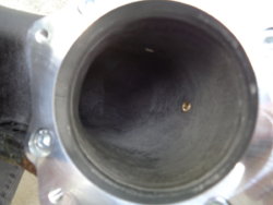
I bought an adapter from NWP. I really didn't want to use one, primarily because it's just more crap and it tappers down to 2.87". Now I have to open this up as I want the 4" reduced to the 3" t.b. to the now 3" neck, then to the plenum. Not a huge deal but more work nonetheless. I removed a fair amount of material from the opening, through the neck and around the bends as it opens up to the plenum using my dremel and sand paper, finishing it off with 1200 grit. I'll open the ass-end of this adapter plate up while on the plenum so it'll be near seamless.
DSC01238.JPG DSC01240.JPG DSC01239.JPG
Photos of after enlarging the tapered adapter plate.
DSC01253.JPG DSC01259.JPG DSC01249.JPG

Here's a quote and dyno chart from a 3.5" intake. It's a 2003 z below on a dynojet, so he's probably around 270hp, 250tq. This chart is from last month (12/17) and the link's here 3", 3.5", & 4" intakes - MY350Z.COM - Nissan 350Z and 370Z Forum Discussion
I was expecting results closer to this as opposed to the 8hp/5tq. I think I'll get now what was still left behind after correcting the jacked up coupler and shortening the intake, and then some. I'm slipping a bit these days, letting some important details fly right over my head.

"Here's the chart. Final numbers from my previous post I had to go look up were +12-13rwhp/+27rwtq. Now, keep in mind a part of this was due to the much cooler air as compared to my first dyno, but there's still no doubting the larger bore Admin intake performs."

YpKTKEm.jpg
 
Last edited:
A couple shots of the lower collector. Don't want to see that again for awhile. T.B. plug from nisformance, the supposed og's of the 75mm mod. I even tapered the pipe edges on both ends to try and get a smooth transition from one piece to the next. Finally, a couple photos of the 75mm t.b.. I'll test it out sometime soon and get a 0-60 and hopefully 1/4 mile. A/F might be a bit lean. I'm not going in for a tune until I install the Tomei headers though, which should be here in a few weeks.
DSC01255.JPG DSC01254.JPG DSC01258.JPG DSC01260.JPG DSC01261.JPG DSC01267.JPG
Smoothed transition on the t.b. and cut the coolant nipples off. Also removed the lip on the outside of the opening which made it difficult to get the coupler on and was distorting it. A view of the 4" intake pipe through the silicone coupler. Smooth transition.
DSC01290.JPG DSC01292.JPG
 
Last edited:
So, a couple weeks ago I made a few minor changes. Found out my intake pipe was too long & the coupler looking like it was jacked up was in fact jacked up. I didn't think it was jacked up but Moncef thought it was jacked up and yeah, I guess it was pretty jacked up. After dealing with this I thought, what other details did my dumbass fail to pay attention to? Looked over the exhaust and found a few. Several pipes were not lined up well along the flanges. Both cats were off quite a bit at the cat-to-invidia junction and several, really every damn pipe was off a little to a lot. A couple minor exhaust leaks as well. Couldn't hear them, but the carbon had visibly passed the gaskets.
After I made these corrections, I went out for a quick 0-60 and got a 5.6 @ 288'. Definite improvement from the last one.
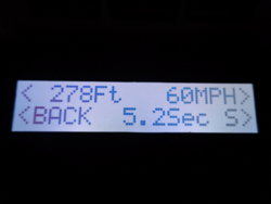
After having done the intake mods above this week and driving the fx for a day, I went out for another 0-60 & got a 5.2 @ 278'. Same slightly inclined road every time. I figured it would perform better and it does. Three very noticeable things; 1. it gets off the line quicker, brake torque or not B. it wants more rpm 3. the exhaust note sounds smoother, little to no snap, crackle & pop.
I shifted later in this run than normal. The gauge is off 3-400 rpm and my redline's set at 6,900. I got lucky this run and must've just missed the rev limiter. It was about 32* during the run so I let the iat's get up a little to attempt to get the best comparison I could. I have a little more work to do with the throttle body and intake pipe this week. This weekend's supposed to be a little warmer, so I'll get another 0-60 but I also want a 60' time & hopefully another 1/4. Don't have any prior 60' times saved anywhere, so nothing to compare to except at the world's shittiest track last year where I got a 2.2, largely stock.
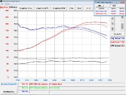
The 1st chart below is one that shows the supposed gains from the 75mm t.b. and the one below that is my last tune. I didn't know what to expect as I've seen a fair amount of negative results with the large t.b. but surmised that these guys fucked up somewhere along the line. Also, the NWP chart just doesn't scream vq35de to me and I still think there's something wrong with it but none of that matters now. I'm just glad I didn't waste my time and $ only to get little to no to negative results. No lean codes or vacuum leaks. No relearn procedures whatsoever with any of this shit I've done regarding the upper/lower collector or 75mm t.b..
Turns out my tuner is still in business which was great to hear. I'd like to get a dyno run in and maybe a little tuning on this setup before I install the headers but that's not practical. Improved times are what it's all about, damn the numbers, but I'm curious to see what the new chart's going to look like and if it'll benefit from adding fuel. The Tomei v2 headers are probably the only worth while shorty headers to install. Beyond these, the right long tubes but you'll get similar results with a good shorty & test pipe combo. I don't want my FX smelling like a lawn mower, nor do I want to draw attention from the po po, so I'm sticking with the high flows.
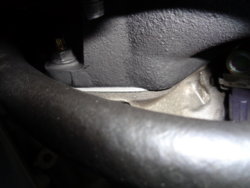
The Aramid iso-thermal spacer is like 5 or more stock gaskets stacked on top of each other. I don't know how minor a detail it takes to affect air flow good or bad, but this spacer adds a little length to the runners and actually helped the lower collector clear some of the b.s. I've got running underneath it from the wire tuck. As I mentioned above, it fits the intake manifold without overlapping runners unlike the stock gasket. I don't expect to see any difference in iat's due to the location of the maf. I bought the gasket on a whim, but I'm not convinced it will help because if the maf doesn't see the improvement, than neither does the ecu.
DSC01286.JPG DSC01288.JPG DSC01287.JPG
NWP-75mm-Big-Bore-Throttle-Body-Dyno-Stock-350z-NonRU.jpg dSx8aUPUqbAJAMY-jYDh2mtFIlbChZELMgCPw1rDXfU-b6eHWz2OOde9f1ARdJDv6NA64urVi-KR1Nw&owa=outlook.live.png
 
Last edited:
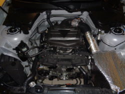
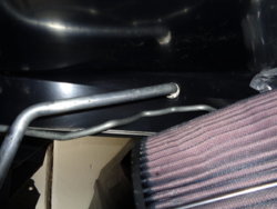
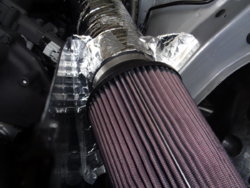
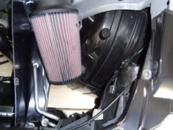
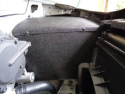
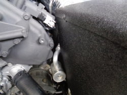
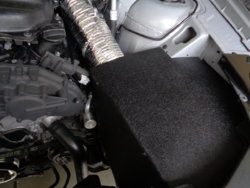
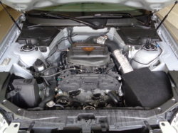
Made a new air box. Went a lot quicker this time. Back is temporarily made from hvac insulation and heat tape until new pipe wrap is installed, then will make a permanent back section. Side is bent and rides on top of the frame. A second scrap piece was fitted and covers two cuts that were necessarily cut into the main side piece just to get the fucker in place. The bottom of the side panel and scrap piece both lock in between the frame and small a/c line. Better fitment and closer to 100% sealed compared to previous box but a little larger, by about 20%. Two fasteners hold the two panels together and it locks into place at three different points. It isn't fastened to the FX anywhere yet doesn't move at all. Original was fitted for a longer pipe and also hugged the top and side of the filter. This one allows much better circulation all around the filter. Color and texture are a very close match to wrinkle painted reservoirs so don't think I'll be painting this one.
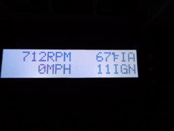
Driving today I noticed that iat's are lower than normal. It's not the air box as it's nothing more than a better looking version of the hvac prototype. It's got to be the Aramid spacer and perhaps more air traveling along the intake tract from porting is partly responsible(?). At idle, it doesn't climb nearly as quickly as it did, even when heat soaked. I went out, shut it down, came back 30 minutes later, started it up and iat's were at 75* and ambient temps were mid 40's. I pulled up to a light and looked at the gauge which read 71*. It just sat at that temp. I started driving and temps went down faster than normal. I don't understand how something post-maf can affect maf iat readings. I have an idea and hopefully MD will answer my question.
DSC01297.JPG DSC01296.JPG DSC01298.JPG DSC01300.JPG DSC01305.JPG DSC01304.JPG DSC01307.JPG DSC01306.JPG DSC01309.JPG
 
Last edited:
Me - I recently bought and installed the Aramid spacer. How does it lower iat's? Having had it on, I can see it does bring the temps down. I never thought it wouldn't do what is claimed, but I don't understand how the information is relayed to the ecu via the maf and how the maf would see reduced iat's with this thermo-mod being located post maf???

T - "The increased density due to the air being cooler means more air is drawn into the engine. When more air is drawn in, it registers on the MAF sensor and this information is relayed to the ECU.
Also, when there is less ping from cooler air, the knock sensor will hear less ping. Less ping is detected by the ECU and the adaptive ECU advances the timing to optimize engine performance.
I hope this helps."
Thank you,
Tony Colette
Motordyne

Sounds like a stupid question and maybe it is to some. His answer is the only thing I thought could possibly be the reason. There's very little heat transfer from my plenum to my MAF, so it's the increase in air passing the maf. I imagine what I did helped the cause but I still find it tough to believe. My idle hasn't increased or decreased prior or post intake modding/aramid spacer, so how much more air could there be? Enough to make a difference I suppose. Guess it doesn't matter, though if this is the deal I expect to see further improvements in iat's, even at idle, once the wrapped headers go on.
 
Last edited:
Made an exhaust note vid to compare the current set up to current + Tomei headers. It's a bit quieter @ idle due to the intake mods which I wasn't expecting or I would've made an exhaust note vid prior to the intake mods. Oh well. Also idle is much lower @ cold start up. This vid was after idling for 5-10 minutes.
Invidia vs Stillen. IMO there's no comparison. Different strokes for different folks.
 
Last edited:
Back
Top