
You are using an out of date browser. It may not display this or other websites correctly.
You should upgrade or use an alternative browser.
You should upgrade or use an alternative browser.
I see BLUE!!!!
- Thread starter rookie
- Start date
gchristopher9
Member
- Location
- Boston MA
next size down would be an 0805, and the next one down from that is 0603. once you get into 0603 and smaller it becomes difficult to work with, and we often use a microscope at work.
shralp
Member
- Location
- San Diego, CA
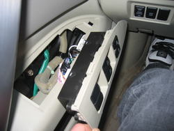
Behind the stereo buttons

To get at the window switches, just yank them out

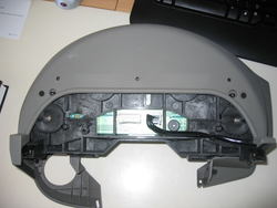
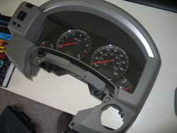
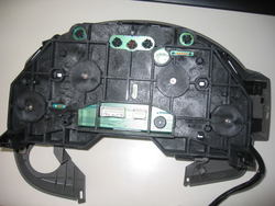
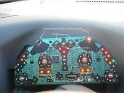
Here's a few shots during the process of taking apart the gauge cluster


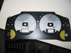
Pop the needles off using 2 spoons to pry it from the gauge. They're on there good

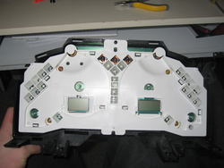
You'll have to sand the white that you can see in this picture. Under the white is the amber color.


The gauge circuit board

To get at the window switches, just yank them out
Here's a few shots during the process of taking apart the gauge cluster
Pop the needles off using 2 spoons to pry it from the gauge. They're on there good
You'll have to sand the white that you can see in this picture. Under the white is the amber color.
The gauge circuit board
Attachments
-
 IMG_3795.jpg83.3 KB · Views: 50
 -
 IMG_3802.jpg94.1 KB · Views: 52
 -
 IMG_3810.jpg92 KB · Views: 57
 -
 IMG_3809.jpg77.4 KB · Views: 83
 -
 IMG_3811.jpg144.4 KB · Views: 51
 -
 IMG_3812.jpg77 KB · Views: 56
 -
 IMG_3813.jpg169.4 KB · Views: 80
 -
 IMG_3814.jpg77 KB · Views: 46
 -
 IMG_3815.jpg83.9 KB · Views: 93
 -
 IMG_3823-1.jpg135.7 KB · Views: 47
Last edited:
- Location
- Southern California
nice write up so far! wow you really going do this huh? might as well since everything is apart . only thing is when you pulled off the needles it may be hard to get them back on "accurately"
. only thing is when you pulled off the needles it may be hard to get them back on "accurately"- Location
- brooklyn, ny
to get the needles back on acurately or close to it, you can power it up & then put the needle where it should be & push it in slightly & see if it rests in the correct position. like, fill the tank then put the needle where it should be filled (if you didn't take an acurate reference before removing it) . speedo at 0 with ign on, temp you can warm it to full operating temp & then about center it, tach if you can see rpms with a meter then match it, then bring it to 2.5K, check if the needles right. can be done to be close enough. the pins will only be in ther proper position when powered though, you can't put the needles back on on the bench
awesome job so far, a lot of patience there.
since you have the gauge cluster apart, can you tell me the thickness of the white bulb shield board in this picture?:

I'm trying to find out how much clearance there is between the circiut board & the rear of the gauge face itself, been meaning to open mine but since you have it apart a rough idea would be helpful if it's convienient
awesome job so far, a lot of patience there.
since you have the gauge cluster apart, can you tell me the thickness of the white bulb shield board in this picture?:
I'm trying to find out how much clearance there is between the circiut board & the rear of the gauge face itself, been meaning to open mine but since you have it apart a rough idea would be helpful if it's convienient
Attachments
- Location
- Westminster OC
- Car
- car
There's a recalibration procedure in the FSM. Take a picture of the needle positions in the reclibration process before taking them off.
- Location
- brooklyn, ny
but there off already :frown:
gotta check the recalibration procedure out though, never knew about that, I usually just make reference sheets before removing
gotta check the recalibration procedure out though, never knew about that, I usually just make reference sheets before removing
- Location
- Westminster OC
- Car
- car

raymond
Member
- Location
- Netherlands
- Car
- FX35 RWD
How can/do you mount those SMD's and PLCC's....?? Can you just "click"them in or do you need to weld it all in...??
And is it just me or can't i see the many lights around the volume button on the circuit board...
Also i read something of an extra LED strip wich be needed to light up the cluster extra as the LED only weren't enough. Any idea where to put those en where to buy or wich to take.....??
And is it just me or can't i see the many lights around the volume button on the circuit board...
Also i read something of an extra LED strip wich be needed to light up the cluster extra as the LED only weren't enough. Any idea where to put those en where to buy or wich to take.....??
shralp
Member
- Location
- San Diego, CA
to get the needles back on acurately or close to it, you can power it up & then put the needle where it should be & push it in slightly & see if it rests in the correct position. like, fill the tank then put the needle where it should be filled (if you didn't take an acurate reference before removing it) . speedo at 0 with ign on, temp you can warm it to full operating temp & then about center it, tach if you can see rpms with a meter then match it, then bring it to 2.5K, check if the needles right. can be done to be close enough. the pins will only be in ther proper position when powered though, you can't put the needles back on on the bench
awesome job so far, a lot of patience there.
since you have the gauge cluster apart, can you tell me the thickness of the white bulb shield board in this picture?:
I'm trying to find out how much clearance there is between the circiut board & the rear of the gauge face itself, been meaning to open mine but since you have it apart a rough idea would be helpful if it's convienient
These pictures are from a couple months ago. I was lazy/frustrated and never posted em. I gave up on this after i blew the circuit board and wired in my own LED circuit.
From what i remember, that white shield is a little less than 1/2" thick and rests right on the circuit board.
shralp
Member
- Location
- San Diego, CA
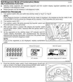
Thanks for that diagnostic thing rookie. Getting the needles back to normal wasn't fun. I left the clear plastic off for a week weeks so i could adjust the needles.
The SMD's need to be soldered in. They have 2 points of contact.
Since there's only 2 twist-lock bulbs lighting up all the gauges you'll have to add some LED's to get the bottom left and right gauges bright enough. Mine are kind of red from the needle LED but i'm satisfied.
The SMD's need to be soldered in. They have 2 points of contact.
Since there's only 2 twist-lock bulbs lighting up all the gauges you'll have to add some LED's to get the bottom left and right gauges bright enough. Mine are kind of red from the needle LED but i'm satisfied.
- Location
- South Gate, CA
- Car
- 2003 FX45 AWD
These pictures are from a couple months ago. I was lazy/frustrated and never posted em. I gave up on this after i blew the circuit board and wired in my own LED circuit.
From what i remember, that white shield is a little less than 1/2" thick and rests right on the circuit board.
So where are you now....? did you have to buy a new board?
Sucks man.. I was waiting for you to finish and see if I could tackel this job on my own by the new year.. just sucks... when you took it apart, where you able to drive your fx with out the dash and/or your radio/nav display...?
shralp
Member
- Location
- San Diego, CA
So where are you now....? did you have to buy a new board?
Sucks man.. I was waiting for you to finish and see if I could tackel this job on my own by the new year.. just sucks... when you took it apart, where you able to drive your fx with out the dash and/or your radio/nav display...?
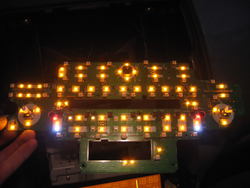
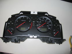
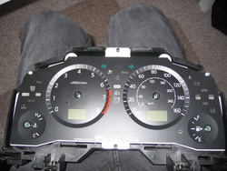
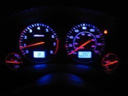
Only parts of the gauge cluster circuit blew so all I was missing was the gauge lights. I took it apart all at once then put it back together before i had to drive again. Here's where i'm at now ....

All the blue lights are from a separate circuit that i wired in. I couldn't find PLCC-4 LED's so i never did the air control display and decided not to try the stereo buttons cause those SMD's are so damn small. Don't let my mishap stop you though. I tried using the wrong twist-lock bulbs for the gauge's and that's what blew the circuit.
Attachments
gchristopher9
Member
- Location
- Boston MA
not to be an @$$ or go off topic. but you should really get some tips on taking photos. especially if you plan on using them in a write up of any sort.
i'm far from a great photographer believe me. My only helpful tip would be to try the macro mode (mine is indicated by a little flower, not sure if this is standard or not) when taking close up photos. Those blurry PCB shots are TOUGH to look at.
i'm far from a great photographer believe me. My only helpful tip would be to try the macro mode (mine is indicated by a little flower, not sure if this is standard or not) when taking close up photos. Those blurry PCB shots are TOUGH to look at.
- Location
- Los Angeles, CA
- Car
- 05 FX35 RWD
That light board is fricken cool all opened up!
Thanks for sharing
Thanks for sharing
shralp
Member
- Location
- San Diego, CA
not to be an @$$ or go off topic. but you should really get some tips on taking photos. especially if you plan on using them in a write up of any sort.
i'm far from a great photographer believe me. My only helpful tip would be to try the macro mode (mine is indicated by a little flower, not sure if this is standard or not) when taking close up photos. Those blurry PCB shots are TOUGH to look at.
Welcome to what i see without my contacts in! I know they're hard to look at but i only posted because someone asked for them. If someone posts better pics i can take these down but in the meantime, this is better than nothing
gchristopher9
Member
- Location
- Boston MA
Yea that is a good point. They are definitely better than nothing that's for sure.
raymond
Member
- Location
- Netherlands
- Car
- FX35 RWD
Shralp, how about those Volume / Channel button lights.....?? In your pics of the circuit board i see those adjustable sticks seam to be lightend from within....
shralp
Member
- Location
- San Diego, CA
Shralp, how about those Volume / Channel button lights.....?? In your pics of the circuit board i see those adjustable sticks seam to be lightend from within....
Those sticks each have 3 SMD's around them, right on the circuit board.
Share: