
You are using an out of date browser. It may not display this or other websites correctly.
You should upgrade or use an alternative browser.
You should upgrade or use an alternative browser.
FX45 electric fan conversion
- Thread starter Logan
- Start date
low88111
Member
- Location
- San Francisco
- Car
- 2004 FX45
not a problem, whenever you get a chance on looking up the A/C clutch connection please post. i have my A/C on almost all the time. thanks


low88111
Member
- Location
- San Francisco
- Car
- 2004 FX45
do you use your AC often? if so do you see any temp changes when used or when ever used? also is that 14 awg/gauge wires your using?
low88111
Member
- Location
- San Francisco
- Car
- 2004 FX45
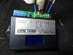
i just received my dakota digital stuff, now im just waiting for the fans, but i was wondering which fan out of the two is considered the "fan high"? would it be the one with more fins?
i also just finished going through the the instructions and its looking like there will be 3 wires that will be taking power directly from the positive battery terminal, i will be feeding the 3 wires to the fuse holder you recommended (from ebay with the 4gauge wire) but would the 40A fuse still be okay or should i get something a little but higher? (i just re read the instructions and it says the controller needs a 12v from the battery, so 4 wires total)
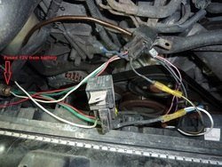
for the green wire on the relay it says "Connect to fused 12V battery circuit that can run cooling fan" i was thinking about connecting that to 12v key in ACC wire with a 10A fuse for each relay, or would the 12v key in RUN be better for this?
LAST Question, where is a good place to mount the controller? i was sitting in my truck yesterday and couldnt find a good spot
i also just finished going through the the instructions and its looking like there will be 3 wires that will be taking power directly from the positive battery terminal, i will be feeding the 3 wires to the fuse holder you recommended (from ebay with the 4gauge wire) but would the 40A fuse still be okay or should i get something a little but higher? (i just re read the instructions and it says the controller needs a 12v from the battery, so 4 wires total)
for the green wire on the relay it says "Connect to fused 12V battery circuit that can run cooling fan" i was thinking about connecting that to 12v key in ACC wire with a 10A fuse for each relay, or would the 12v key in RUN be better for this?
LAST Question, where is a good place to mount the controller? i was sitting in my truck yesterday and couldnt find a good spot
Last edited:
I use the more blade fan as hi fan. The fused 12V for the controller module should not be taken from the same 40A fused 12V. It should be coming from a separate 12V source instead.
I wire two green (from relay) and two red (from relay) wires to the 40A fused 12V. If you connect the relay green wire to ACC, the fan can only run when the key is in ACC or the car is running. In my opinion, that's not ideal. Since you can set the controller to keep the fan running for a number of second after the car is off, it would be best to power the relay green wires to the 40A fused 12V.
I tuck the controller somewhere near the parking brake paddle.
low88111
Member
- Location
- San Francisco
- Car
- 2004 FX45
thanks a million, glad to hear that glass holder with 40a fuse can handle the four wires. i was thinking a 10a fuse for the controller or should i just stick a 15a in there? the fan should be in on monday after that i just have to find a day or night to hook it all up.
*I was going to buy a few things from amazon, they have the fuse holder with the 4 gauge wire you suggested, but they come with a 60A fuse insted of a 40A. would the 60A be to high for our application ?
*I was going to buy a few things from amazon, they have the fuse holder with the 4 gauge wire you suggested, but they come with a 60A fuse insted of a 40A. would the 60A be to high for our application ?
Last edited:
low88111
Member
- Location
- San Francisco
- Car
- 2004 FX45
So i picked up the fan in yesterday from ups and partsgeek says it doesn't come with a wiring harness for the 2 fans even though in the pics it clearly shows it does. i could have bought another fan from somewhere else and gotten the wiring harness with it, but im not interested in shipping the fan back to them out of my pocket and paying a re stocking fee. now i have to order the wiring harness.
But if you are interested, i have narrowed down the a/c clutch connection to either the wire coming off of #11 (2004 Infiniti FX45 Base Condenser, Compressor & Lines) or where ever this hooks up to (2003 Infiniti FX45 HVAC Pressure Transducer - Global Parts 1711553 or [Dead Link Removed])
I really want to hook this wire up because my a/c never turns off. as soon as i turn it off the truck gets all hot and feels humid real quick inside
Let me know what you think la_fx35
Last edited by a moderator:
low88111
Member
- Location
- San Francisco
- Car
- 2004 FX45
Okay so I just go the oem fan harness for a 35 in today (finally). But in one set I have blk, blk/wht, blk/yel, and wht and other set is blu, blu/wht, red/wht and red/blu. I dont know which wire the black wire from the relays connect to. Also out of the wires on the harness, i dont know which two of them are the ground. Are you familiar with the 35 fan harness la_fx35? If so please shed some light
Thanks again
Thanks again
low88111
Member
- Location
- San Francisco
- Car
- 2004 FX45
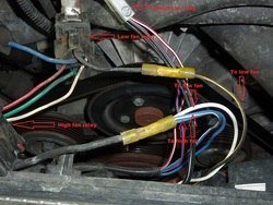
i was going through the FSM and to test the motors on the fan they said hook up power to 1&2 and ground 3&4 (on the female 4-pin connector) so i would be hooking up 2 wires to the black wire on each relay and grounding the other 2? i was looking the the pic Logan posted but cant really tell which wires got connected to the relay. does he still frequent the fourm? but i attched some pic if it would help


Attachments


Last edited:
low88111
Member
- Location
- San Francisco
- Car
- 2004 FX45
i also went to the wiring diagram section, and it mentions the fan wiring harness has green wires which i dont have?????
low88111
Member
- Location
- San Francisco
- Car
- 2004 FX45
bump
low88111
Member
- Location
- San Francisco
- Car
- 2004 FX45
la_fx35 when you have some time, can you check what pin out of the four is connected to the black wire on the relay and which pin is the ground? i would hate to have to start looking around for a shop to put it in now after i bought all the necessary supplies and its pretty straight forward after this hurdle for me. Thanks again
Last edited:
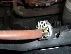
Fan Wiring:
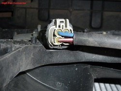
Red/White & Red/Blue wires of High fan to ground
Black/White & Black wires of Low fan to ground
40A Relay for Low Fan:
Green(87) & White(86) to fused battery 12V
Red(85) to Dakota controller Low fan
Black(30) to Black/Yellow on the Low fan
70A Relay to High Fan:
Green(87) & Red(86) to fused battery 12V
White(85) to Dakota controller High fan
Black(30) to Blue wire, Blue/White wure on the High fan, and White wire on the Low fan
Attachments
-
 P1090233_zpspw73zw3f.jpg228.5 KB · Views: 112
 -
 P1090233_zpspw73zw3f.jpg228.5 KB · Views: 67
 -
 P1090232_zpsrni6rhb5.jpg168.3 KB · Views: 83
 -
 P1090232_zpsrni6rhb5.jpg168.3 KB · Views: 83
 -
 P1090231_zpsz6eobyuo.jpg178.4 KB · Views: 115
 -
 P1090231_zpsz6eobyuo.jpg178.4 KB · Views: 62
 -
 P1090239_zpsdwib7xdp.jpg208.2 KB · Views: 114
 -
 P1090239_zpsdwib7xdp.jpg208.2 KB · Views: 67
low88111
Member
- Location
- San Francisco
- Car
- 2004 FX45
Good observation on the lower amp relay red and white wires being switched around, mines came like that too, you would think they would have fixed that by now. Okay so let me get this straight. By looking at your pic and reading your description, the white wire from the low fan will be getting hooked up to the high fan relay making 3 wires going to the black wire on the high fan relay. I was just wondering, why is that opposed to the white wire following the black/yellow? Does that mean the low fan can only turn on when the high fan is also on?
But Thank You I cant wait to get started on this, I just moved and im in the unpacking stage, I have more stuff than I realized :doh:
But Thank You I cant wait to get started on this, I just moved and im in the unpacking stage, I have more stuff than I realized :doh:
aordonio
Member
- Location
- United States
- Name
- Andre Ordonio
excellent write up / can't wait to do this - this is on my list of upcoming things "to do."
biggman440
Member
- Location
- Columbia,SC
Im trying to do an electric fan conversion on my 05 FX45. Can someone point my in the right direction since its an older vehicle? Thanks Guys
Share: