- Location
- Portland, OR

You are using an out of date browser. It may not display this or other websites correctly.
You should upgrade or use an alternative browser.
You should upgrade or use an alternative browser.
Jumbo Boost
- Thread starter jumbosrule
- Start date
raymond
Member
- Location
- Netherlands
- Car
- FX35 RWD
You should replace the entire timing chain assembly based on your mileage. VTC sprockets will show some age as well, I put in Nismo VTCs and was surprised at the marks on the original VTC sprocket teeth.
Rook, where would lie the Miles border to do this....?? To make sure would changing the chain anyway be advisable...??
Jumbo,
Will you be staying at your oem headers...?? Or go for aftermarket....??
Rook, where would lie the Miles border to do this....?? To make sure would changing the chain anyway be advisable...??
Jumbo,
Will you be staying at your oem headers...?? Or go for aftermarket....??
My shop inspected the VTCs and chain. They recommended a new timing chain, but said the VTCs looked fine - no need to change.
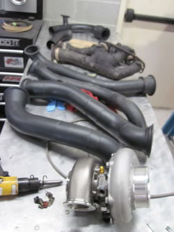
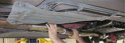
I'm using the OEM exhaust manifold from a G35 - a car that had a custom turbo system installed and dyno tested to 550whp. I'm using the OEM headers and several parts of the G35 setup - but modifying other parts to fit the FX. Here are the G35 parts. My OEM wrapped headers and new turbo are on the table too:

Attachments


Love it. Maybe all caps?
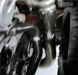
Ok so I visited the shop yesterday and only took a couple photos. The piping has been cut and laid out from the exhaust manifolds all the way to the turbo. They have also found placement for the turbo and will hard-mount it to the chassis.
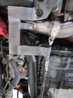
Here's a shot of the merge collector. Just before the new fab begins:
View attachment 200317
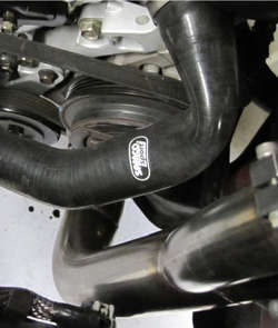
All the new fab has not been ceramic coated so the existing G35 kit is black and the new fab is bare metal - only tacked together at this point.
View attachment 200319
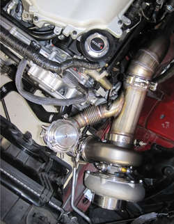
Here's another shot - looking up towards where the CAI used to be:
View attachment 200321
The V-band connection above will connect to this next piece, which mates up to the turbo just above the flex section. The short tube I'm holding in place is for the wastegate, which will be recirculated into the exhaust to control sound & heat in the bay. We will most likely remove and re-route the large radiator hose to keep it away from the turbo heat.
View attachment 200323
By the time I show up next Tuesday, I expect the turbo to be installed in the bay. Can't wait for those photos!
Last edited:
- Location
- Dallas, TX
- Car
- 2007 FX35 RWD
Very cool! Looking forward to the next batch of photos.
- Location
- Southern California
I love the updates in all the threads 
gmgagne
Member
nice!
Ok - picking up exactly where I left off with the last post. The shop has put a solid two days of work into the hot side fab. The last photos I posted were the exhaust paths merged into the turbo feed.
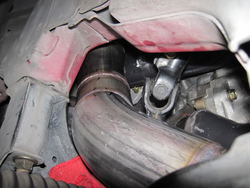
This next shot is of the up-pipe (sorry for the freakin focus):


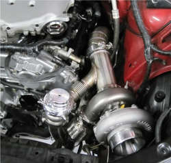
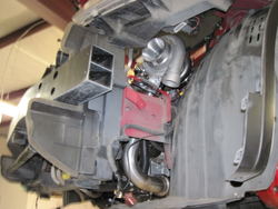
That pipe leads up to all the goodies. The turbo is solid mounted to the frame of the FX. This next picture almost made me bust out my "O" face.

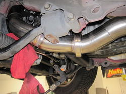
The turbo exhaust is a 3" downpipe and it is hard to take good photo of that. But that 3" pipe runs all the way to the Stillen 3" merge.

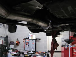
The car was lifted and I got a shot of where the downpipe turns towards the exhaust:

The next few shots are more of the work currently going on when I was there - will be completed with a few more hours of work.


There are still some small obstacles to overcome. First of all, the air inlet for the turbo is in very tight quarters. The goal is to route the intake filter into the space in front of the wheel well. There will most likely need to be some trimming of OEM baffles around the headlight, but the shop thinks they have enough room to work with.
The chassis brace needs a lot of work. It's in the way but needs to stay there, so the shop is cutting and welding it so that it will avoid the new plumbing and still do it's job. Still plan to get the new GTSpec mid-chassis brace, so I hope the combination of the two will be more than I really need. The GTSpec ladder brace also interferes, so can't use that.
Still will address heat with all kinds of shielding, moving lines, hoses & whatever makes sense.
They mentioned that they don't want the lowest point on the car to be something they installed. I like that thinking.
One of the things they talk about each time I see them is how it will be "easy" to take apart the system for maintenance reasons. Hope so! Will most likely be doing my own oil changes from now on - I just can't trust any old shop anymore. For a couple reasons.
Will need to pick the oil I plan to run after the break in, then provide it to any place I trust enough.
Powerfab recommended a replaceable cartridge oil filter system. The oil warmer lines were already removed from my filter fitting, so we plan to remove that adapter/sandwich and install a rather large oil filter "housing" that I will remove, pop out the old cartridge, put in a new one, then put it back on the motor each time it's time for a change. The one major design difference between this filter and the OEM version is that there is NO bypass for this new filter. All oil is filtered all the time. We all agree no bypass is really important for the break-in of the engine.
After the initial safe tune, I'll do a minimum 500 miles of normal driving. Then it goes back to the shop for another couple weeks. "Special sauce" - they call it. :ninja:
Looooollll.
Whoa. Just channeled Dopie there.
And on that note...
This next shot is of the up-pipe (sorry for the freakin focus):
That pipe leads up to all the goodies. The turbo is solid mounted to the frame of the FX. This next picture almost made me bust out my "O" face.
The turbo exhaust is a 3" downpipe and it is hard to take good photo of that. But that 3" pipe runs all the way to the Stillen 3" merge.
The car was lifted and I got a shot of where the downpipe turns towards the exhaust:
The next few shots are more of the work currently going on when I was there - will be completed with a few more hours of work.
There are still some small obstacles to overcome. First of all, the air inlet for the turbo is in very tight quarters. The goal is to route the intake filter into the space in front of the wheel well. There will most likely need to be some trimming of OEM baffles around the headlight, but the shop thinks they have enough room to work with.
The chassis brace needs a lot of work. It's in the way but needs to stay there, so the shop is cutting and welding it so that it will avoid the new plumbing and still do it's job. Still plan to get the new GTSpec mid-chassis brace, so I hope the combination of the two will be more than I really need. The GTSpec ladder brace also interferes, so can't use that.
Still will address heat with all kinds of shielding, moving lines, hoses & whatever makes sense.
They mentioned that they don't want the lowest point on the car to be something they installed. I like that thinking.
One of the things they talk about each time I see them is how it will be "easy" to take apart the system for maintenance reasons. Hope so! Will most likely be doing my own oil changes from now on - I just can't trust any old shop anymore. For a couple reasons.
Will need to pick the oil I plan to run after the break in, then provide it to any place I trust enough.
Powerfab recommended a replaceable cartridge oil filter system. The oil warmer lines were already removed from my filter fitting, so we plan to remove that adapter/sandwich and install a rather large oil filter "housing" that I will remove, pop out the old cartridge, put in a new one, then put it back on the motor each time it's time for a change. The one major design difference between this filter and the OEM version is that there is NO bypass for this new filter. All oil is filtered all the time. We all agree no bypass is really important for the break-in of the engine.
After the initial safe tune, I'll do a minimum 500 miles of normal driving. Then it goes back to the shop for another couple weeks. "Special sauce" - they call it. :ninja:
Looooollll.
Whoa. Just channeled Dopie there.
And on that note...
Attachments
-
 IMG_6441.jpg33.6 KB · Views: 8
 -
 IMG_6441.jpg33.6 KB · Views: 6
 -
 IMG_6446.jpg84.7 KB · Views: 8
 -
 IMG_6446.jpg84.7 KB · Views: 8
 -
 IMG_6436.jpg46.5 KB · Views: 8
 -
 IMG_6444-1.jpg32 KB · Views: 86
 -
 IMG_6444-1.jpg32 KB · Views: 8
 -
 IMG_6436.jpg46.5 KB · Views: 8
 -
 IMG_6451.jpg88.7 KB · Views: 8
 -
 IMG_6451.jpg88.7 KB · Views: 7
 -
 IMG_6452.jpg83.5 KB · Views: 10
 -
 IMG_6452.jpg83.5 KB · Views: 12
 -
 IMG_6453-1.jpg34.6 KB · Views: 8
 -
 IMG_6453-1.jpg34.6 KB · Views: 8
 -
 IMG_6441.jpg33.6 KB · Views: 8
 -
 IMG_6444-1.jpg32 KB · Views: 7
 -
 IMG_6451.jpg88.7 KB · Views: 12
 -
 IMG_6436.jpg46.5 KB · Views: 7
 -
 IMG_6446.jpg84.7 KB · Views: 10
 -
 IMG_6452.jpg83.5 KB · Views: 10
 -
 IMG_6453-1.jpg34.6 KB · Views: 8
 -
 IMG_6444-1.jpg32 KB · Views: 13
 -
 IMG_6441.jpg33.6 KB · Views: 9
 -
 IMG_6441.jpg33.6 KB · Views: 8
 -
 IMG_6446.jpg84.7 KB · Views: 11
 -
 IMG_6436.jpg46.5 KB · Views: 7
 -
 IMG_6436.jpg46.5 KB · Views: 10
 -
 IMG_6444-1.jpg32 KB · Views: 9
 -
 IMG_6446.jpg84.7 KB · Views: 6
 -
 IMG_6452.jpg83.5 KB · Views: 11
 -
 IMG_6451.jpg88.7 KB · Views: 12
 -
 IMG_6452.jpg83.5 KB · Views: 10
 -
 IMG_6453-1.jpg34.6 KB · Views: 8
 -
 IMG_6453-1.jpg34.6 KB · Views: 9
 -
 IMG_6451.jpg88.7 KB · Views: 7
 -
 IMG_6441.jpg33.6 KB · Views: 8
 -
 IMG_6452.jpg83.5 KB · Views: 9
 -
 IMG_6453-1.jpg34.6 KB · Views: 8
 -
 IMG_6451.jpg88.7 KB · Views: 8
 -
 IMG_6446.jpg84.7 KB · Views: 7
 -
 IMG_6444-1.jpg32 KB · Views: 5
 -
 IMG_6436.jpg46.5 KB · Views: 11
- Location
- Portland, OR
Word. That air filter location is a bitch but I imagine it will be worth the hassle. I tossed around the prospect of building a little trap door into the fender liner to allow access to the filter down in the fender area. It would only require removal of the front drivers side wheel rather than the whole bumper or intake tract, but it didn't make my "short list" of things to do...
Great pics!!! I'm excited to see the raging burnouts!
Posted from my BlackBerry using BerryBlab
I tossed around the prospect of building a little trap door into the fender liner to allow access to the filter down in the fender area. It would only require removal of the front drivers side wheel rather than the whole bumper or intake tract, but it didn't make my "short list" of things to do... Great pics!!! I'm excited to see the raging burnouts!
Posted from my BlackBerry using BerryBlab
- Location
- brooklyn, ny
wow, looks great, nice to see it all come togeather, just a little more patience, she's almost there.
I hate to be the one to tell you this & I hope I'm wrong, but I'm pretty sure your going to get a lot of vibration transfer from the way that's set up though, that flex piping isn't going to be enough to isolate that I think. remember what it felt like with solid mounts? well probably no where near as bad as that was, but there will be some vibration transfer there I think. that big turbo really looks so great in there though, coming out really nice, I bet you can't wait to hear her whistle & purrr :smile (2):
I hate to be the one to tell you this & I hope I'm wrong, but I'm pretty sure your going to get a lot of vibration transfer from the way that's set up though, that flex piping isn't going to be enough to isolate that I think. remember what it felt like with solid mounts? well probably no where near as bad as that was, but there will be some vibration transfer there I think. that big turbo really looks so great in there though, coming out really nice, I bet you can't wait to hear her whistle & purrr :smile (2):
The turbo is mounted to the bracket that was originally meant for the OEM airbox, so it's not directly on the chassis, plus it's about as far forward as it can go. I can understand if there is some vibration and if it's too much for me, I'll have the shop work on some isolation for it. But I'll cross that bridge if I need to.
Been a few days since you posted, Turbo - hope your project is moving forward too!
Been a few days since you posted, Turbo - hope your project is moving forward too!
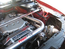
Visited the shop yesterday but not a whole lot of changes from last visit. The hot side and exhaust are complete - fully welded:


And the bumper has been removed to begin working on the intercooler installation - which should be well under way at this point today.
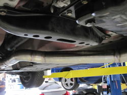
Here's a shot of where the IC pipe will route and also where the air filter will be located. You can also see how the turbo is hard mounted:

and so is the 3" exhaust pipe all the way back to the Stillen merge collector. Here's a shot of the modified chassis brace. It had to be cut to miss the hot side pipes, and it was made into a gard for the V-band clamp as well as a mount for the exhaust:

Shop says that the cold side shouldn't take much more than a day to complete. Tuning begins tomorrow.
And the bumper has been removed to begin working on the intercooler installation - which should be well under way at this point today.
Here's a shot of where the IC pipe will route and also where the air filter will be located. You can also see how the turbo is hard mounted:
and so is the 3" exhaust pipe all the way back to the Stillen merge collector. Here's a shot of the modified chassis brace. It had to be cut to miss the hot side pipes, and it was made into a gard for the V-band clamp as well as a mount for the exhaust:
Shop says that the cold side shouldn't take much more than a day to complete. Tuning begins tomorrow.
Attachments
-
 IMG_6461.jpg72.2 KB · Views: 9
 -
 IMG_6462.jpg73.4 KB · Views: 9
 -
 IMG_6462.jpg73.4 KB · Views: 9
 -
 IMG_6461.jpg72.2 KB · Views: 7
 -
 IMG_6458.jpg80.4 KB · Views: 12
 -
 IMG_6463.jpg70.6 KB · Views: 8
 -
 IMG_6458.jpg80.4 KB · Views: 8
 -
 IMG_6463.jpg70.6 KB · Views: 8
 -
 IMG_6461.jpg72.2 KB · Views: 8
 -
 IMG_6462.jpg73.4 KB · Views: 11
 -
 IMG_6458.jpg80.4 KB · Views: 9
 -
 IMG_6463.jpg70.6 KB · Views: 7
 -
 IMG_6462.jpg73.4 KB · Views: 20
 -
 IMG_6461.jpg72.2 KB · Views: 8
 -
 IMG_6461.jpg72.2 KB · Views: 7
 -
 IMG_6463.jpg70.6 KB · Views: 10
 -
 IMG_6458.jpg80.4 KB · Views: 8
 -
 IMG_6462.jpg73.4 KB · Views: 8
 -
 IMG_6458.jpg80.4 KB · Views: 6
 -
 IMG_6463.jpg70.6 KB · Views: 7
 -
 IMG_6461.jpg72.2 KB · Views: 9
 -
 IMG_6462.jpg73.4 KB · Views: 8
 -
 IMG_6458.jpg80.4 KB · Views: 8
 -
 IMG_6463.jpg70.6 KB · Views: 9
- Location
- Westminster OC
- Car
- car
That brace probably doesn't do that much but why did they have to hack it up? Was the piping from a G35 running a GT42?
The piping came from a custom G turbo setup, which did not have that brace. When they fit it up it was either mod the brace or make new pipes.
- Location
- Westminster OC
- Car
- car
Yeah the G/Z don't have that cross member. I think I know the G this was used from. User name on driver is/was citco. Guy had a questionable attitude.
Yeah the G/Z don't have that cross member. I think I know the G this was used from. User name on driver is/was citco. Guy had a questionable attitude.
Yes - that's the G some of these pipes came from. In reality, all we kept were the two exhaust manifolds, cross pipe and merge collector. Everything else on the hot side was custom fabbed for the FX. Easy to see what came from the G because it is already ceramic coated black. The cold side was polished on the G - I plan to have the cold side silver ceramic coated.
That G is now back at Powerfab, going with bigger and better stuff, I've been told. Never met the owner, but he did sell me all the piping from his old G setup for a pretty good price.
I saw your post in his thread back when this was all coming together. Sort of funny to know you have some history with my turbo setup before I did!
Last edited:
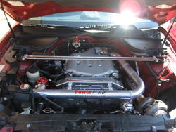
Intercooler piping and a base map tune were finished up to allow the break-in of the motor. Got a minimum of 500 miles to go before taking it back for ceramic coatings and a power tune. So far I'm loving it.


Attachments
-
 IMG_2586.jpg107.8 KB · Views: 14
 -
 IMG_2586.jpg107.8 KB · Views: 6
 -
 IMG_2584.jpg88.1 KB · Views: 9
 -
 IMG_2584.jpg88.1 KB · Views: 6
 -
 IMG_2584.jpg88.1 KB · Views: 10
 -
 IMG_2586.jpg107.8 KB · Views: 9
 -
 IMG_2586.jpg107.8 KB · Views: 9
 -
 IMG_2586.jpg107.8 KB · Views: 10
 -
 IMG_2584.jpg88.1 KB · Views: 11
 -
 IMG_2584.jpg88.1 KB · Views: 10
 -
 IMG_2586.jpg107.8 KB · Views: 10
 -
 IMG_2584.jpg88.1 KB · Views: 12
- Location
- Dallas, TX
- Car
- 2007 FX35 RWD
Lookin' good!
Ceramic coating will keep the intake piping from getting hot as it goes over the turbo, right?
Ceramic coating will keep the intake piping from getting hot as it goes over the turbo, right?
Share: