onthemove MOD's

I started to do the passenger harness realized the wires were not long enough, put everything back and never went back to tackle it.

This might spur me to do that. Excellent work.
 
I started to do the passenger harness realized the wires were not long enough, put everything back and never went back to tackle it.

This might spur me to do that. Excellent work.
Thank you. I started w/the driver side. Mistake. Passenger side best to start on, imo. 1/2 the wires don't need extending. I added to the pass. side notes that the fog light on that side is long enough as well.
 
Dealt with two of my own grounds & power to alternator. There's an existing hole down there, just have to enlarge it to 1" & fit a grommet. 1" or 1 1/8" hole saw & tapping oil does the trick. Vinyl plugs from Lowes fill the 2 old holes on passenger side & 1 hole on driver side. 2 old cuts for my 2 added grounds, which were relocated, are the only marks left behind from all the surgery.
DSC00531.JPG
Inside the battery bay. Used perm. gasket maker to seal & make sure the grommet stays locked in place for this alternator power line (on the right). Trans. plug (oem & on the left) converted to grommet is beefy & very tight-fitting compared to these aftermarket grommets, hence the gasket maker insurance policy. My added trans. ground ran between trans. power loom & grommet. Snug but not too tight.
DSC00523.JPG
Large blue/grey plug for accessories was routed completely under the intake, along with ground from timing chain cover to t.b.
DSC00532.JPG
Ground from batt. to t.b., t.b. to trans & t.b. to timing chain cover. Had all grounds @ one point but these are the only added grounds necessary imo. Stereo improved & so is transmission. Replaced ground from muffler to chassis & improved all other oem grounds. DSC00533.JPG
All necessary equipment for the fucking tucking & 2 bags full of useless crap I've been collecting since I started modding this thing. www.wiringproducts.com has quality automotive wire in various lengths, good from 140 to 180 degrees. Go get u some son.
DSC00529.JPG
Finished product except for timing chain cover & accessories, until I build, then brake lines & whatever else can be dealt with will be dealt with.
DSC00530.JPG
 
Last edited:
Making this shift mod redux post my home base for all that is, was & will be "onthemove". Hopefully some will find some of the info I post useful or @ least entertaining. Read many who claim the various aftermarket intakes are of little value. I beg to differ. I'll post some dyno results of the before & after of my custom 4" later. Will focus on intake temps which is a general aspect regardless of induction method, be it forced or N.A.. Was looking at gauges & what is actually needed to monitor & discovered scanguage 2 has some of what's useful & I can add to it which is a different topic. One function it monitors is the air intake temps via the MAF so I set it to that & selected a few others. I can see 4 functions at a time & it's directly plugged into the ecu port. Tonight it was a somewhat humid but still a comfortable 76*.
DSC00538.JPG
This was the temp. of the air entering my engine @ idle on after driving 15 minutes & idling for 5, bottom left w/the a/c on to get temps up & fan going. Top left is rpms & more accurate than the oem gauge per my tuner. OEM off 3-400 rpms. MPG's on the top right (far more accurate than oem) & timing bottom right. Many more options w/this thing. 0-60, 1/4 mile, 60-0 stopping times & more can all be recorded. It doesn't start timing until ecu reads motion (or braking for the 60-0 timer). I love this thing. Need to figure out how to program for trans & engine oil temps & oil pressure.
DSC00537.JPG
That's ridiculous. That's a double on the ambient & totally unacceptable. I noticed the other day how much hotter the I.A. was as compared to the ambient temps. So, I did some research & found two others, one w/a miata & the other a 350z, both with scangauge2's & both showing obscene I.A.'s. The MAF/ECU reads roughly 7-10* hotter than ambient for whatever reason & I know this because I can see the temps. as soon as I turn the key, cold engine. Not sure if there's a hiccup between the scangauge & ECU or what, but I've got a base & that's all that matters.
So, time for a prototype CAI conversion for the long 4" fatty pipe.
DSC00534.JPG
DSC00535.JPG
DSC00536.JPG
Made this in about 10 minutes. There's several points in the bay where it locks itself into place. No tape holding it to the bay. Drove it running some errands & temps were 15-20* lower, whether driving or idling yesterday. Same outside temps both days. It's a thicker than average gauge box so it does have some insulating properties to it which were obvious afterwards, though the difference could've been entirely from the "heat shield" effect, not blocking radiant heat but hot air. Radiant heat is really an issue with the aluminum pipe & is with plastic as well. Before the plasti-dip on the pipe, I couldn't touch it after driving & after the dip I can, so it helps but not enough.
The key is not just to get cooler air into the intake but also to convince the MAF that it's not seeing hotter air so it will stop pulling timing. I think resolving this issue will resolve the majority of heat-soak related power loss. An "air box" will be great for calming down the air @ the filter. The radiator fans definitely cause issues, just take a leaf blower & get close @ idle, not too mention hot air.
One thing to consider from the quotes below is that Mr. Motordyne is referencing testing on a dyno. For those who haven't been on a dyno yet, the hood is up w/a monster fan blowing 2' away from the radiator. When do you have such a situation on the road? Never, especially @ idle. I think the benefits are greater than what's written below...

An interesting take on the subject from a guy who ought to know;
Hydrazine
MOTORDYNE-MY350Z SPONSOR
upload_2017-8-30_21-43-32.jpeg
" I've noticed while on the dyno the intake temps increased over time. I found it was due to heating of the MAF housing and the back side of the stock air box.
At idle, between dyno pulls, the radiant heat would increase air intake temperatures by ~20'F. 20'F is a lot! It would heat up the entire intake tract and MAF sensor. And when I did the dyno pull, it would take several seconds for the MAF sensor to cool down... but by then it was too late.
The ECU adjusts spark timing based on air intake temperature. Consequently HP is directly affected by timing AND air temperature (IE air density).
And this was all because of heat soak between dyno pulls. It would cause dyno results to go down by 5-10 HP as the air intake system became heat soaked.
For the purposes of R&D dyno testing of air intake and exhaust modifications, the heat soak would throw off the accuracy of pre/post dyno testing, so I simply had to eliminate the heat soak.
I wraped the air intake and it helped stabilize temperatures and dyno results quite a bit.
It was exactly what I needed.
On the road, it won't make too much of a difference for continuous driving but it will help at the 1/4 mile track or any situation where you need to sit at idle for a length of time before launching."

And;

Hydrazine
MOTORDYNE-MY350Z SPONSOR
upload_2017-8-30_22-45-0.jpeg
Quote: Originally Posted by chamois
Thanks for the input. I found a website that said for every 11 deg. F the temp. drops you gain 1% in power. not huge gains maybe 2-4 hp but by using a $15 reflective tape or something from a hardware store it might help out a little bit. and the pic gothchic put up doesnt look to bad.
" Yes, 11 deg F = 1HP
And that only takes into account air density... If its air temperature as seen by the MAF, it makes even more of a difference."
 

Attachments

  • upload_2017-8-30_22-45-0.gif
    upload_2017-8-30_22-45-0.gif
    996 bytes · Views: 128
Last edited:
  • Like
Reactions: gto
Interesting work, what do you plan to make the final out of? Aluminum? Plexi? I tried to make a CAI by putting the filter down behind the foglight since I had removed the OEM airbox resonator. But couldn't get the piping to work - heat shield/box is a great idea though.
 
Interesting work, what do you plan to make the final out of? Aluminum? Plexi? I tried to make a CAI by putting the filter down behind the foglight since I had removed the OEM airbox resonator. But couldn't get the piping to work - heat shield/box is a great idea though.
Thanks. I want to get things like this out because there's so much info available but it takes awhile to figure out who is right. There's two 4" intakes on the market from 2 different tuning companies. One's a 3.5" & the others a 4". They both make power above & beyond all others. Ones administration tuning (3.5") I think? Then there's the furookie & injen, both I think are 3.5"? All of these tmk need to be tuned. My FX ran roughly for a few seconds & that was it until I got it tuned.
I like both the Fur. & Inj.. As you mentioned putting the filter behind the fog light is a great idea & both these better known makes do this somewhat. One problem w/this is there's a thought behind the pipe being as straight as possible & as long as possible. This brings the air in "straighter", so to speak, which is interesting because that's the theme behind K&N's air filters, in that they "straighten" out the air & let more of it on. The other problem is there's still no heat shield for most/any of these. Your still taking in hot engine bay air & the exposed radiator fans will throw things of @ idle. You've also got the radiant heat issue blasting the pipe & the MAF.
The bottleneck of the t.b. seems to be of no consequence & a larger t.b. is probably a waste of time.
I'm using the bubble-wrap style foil back insulating material from Lowes rated for 180* & heat tape. Small role + tape = $20 to find out how well it works. I've found others had success w/this product & I think the insulating property will go above & beyond the gold tape seen most often by shops, especially for the pipe itself, though it'll probably look odd. We'll see tonight. I plan to incorporate the MAF into the insulation. I relocated the MAF close to the t.b. for more accurate tuning & read the "straighter" air closest to the t.b. but now it's even closer to the heat source & that sucks ass.
I find it interesting, the amount of power lost believed by Mr. Motordyne is 5-10 though we can all feel that heat soak, can't we? Then again, he's on a dyno w/the hood up & fan blowing. I know I feel a big difference driving in the fall as opposed to summer. I think the higher the hp the greater the effect & for us bolt-on FX's, I bet on a summer day, were losing 15-20.
The issue w/the two intakes reference above by not-so-well-known tuners is that I think they both delete the pcv on both sides. I know the 4" one does. That's no good.
 
Last edited:
Took the material...DSC00546.JPG
and started w/the intake. Notched out for the pcv bung & incorporated the MAF into the insulation. Overlapped the seem which runs down the front which was the best way to include the MAF w/out too much work. No tape is stuck to the intake, bung or MAF.
DSC00550.JPG DSC00549.JPG
DSC00551.JPG
DSC00555.JPG
DSC00554.JPG
Installed new + & - terminals before I got started. Oem's failed. -'s been rigged for awhile & + went after wire tuck.DSC00541.JPG
Also finished cleaning & painting the timing chain cover & cam sensors. Looks deeper black in person. It should last & it actually turned out pretty well if I don't say so myself, which I just did. Did the heat shields on the exhaust manifolds a couple months back & they look as they did from day 1. Not exactly car show winning quality but for now a hellofalot better than all the oxidation. Also gives me a chance to let the color choice soak in as I plan to have it done this way, except in high gloss powder coating. Everything that's not painted black would be p.c. silver or better yet, clear p.c. over clean aluminum. Every thing under the hood will get a face lift @ that point. Must have some patience & too much time on your hands to dick around with this but I couldn't help myself. @ least the s.c. or turbo will look decent in this bay for the time being.
DSC00543.JPGFront passenger side 1/2 shaft seal leaking. See the cardboard:(
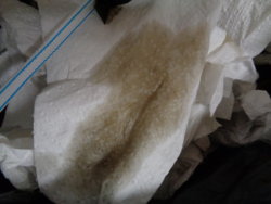
? Thought is was engine oil seepage for awhile which is ultimately what lead to everything cosmetic that's been done under the hood. I got under the bay & cleaned the shift out of everything using gunk & after, brake cleaner. I was surprised & happy to find this seal leaking as I thought it was the upper oil pan prior to this. Had a tire out-of-round (.025) that I think (cannot prove) fucked my wheel bearing which then lead to the failed seal. Replaced both front wheel bearing assemblies. Not fun. That's what I get from replacing my Pirelli's w/Kumho's. Wha wha wha.
DSC00542.JPG You can see the remnants of the original test patch:cry:. Great.DSC00544.JPG
 
Last edited:
Now that the intakes wrapped, I installed it & did the heat shield but 1st another detailed shot of my artist paint brushed po man's paint job & modified pcv intake hose...
DSC00545.JPG DSC00553.JPG
So here's the heat shield. A little ricey? I'll take mine w/shrimp or oooh, orange chicken! Lots of triming & on/off to get it to fit. Got brake lines & a/c line bracket on the frame. I did tape it to the frame. The heat tape is extremely sticky. Acetone cleans the surface well beforehand. The shield can easily be lifted away from the fender while still attached to the frame for cleaning the filter.
The heat tape doesn't show up nearly as well in person. MAF plugged in w/out interference.
DSC00557.JPG
Cannot tell it's taped to the frame. A little tape here & there @ my cuts to maneuver around all that's attached to the frame. Other than @ the frame the only other area that's taped is 1 small piece, top right near the headlight just for piece of mind though not necessary. It somewhat locks into place behind the headlight.DSC00564.JPG
Heat shield below the frame as well, taped underneath the wheel well plastic on 3 sides. It should hold just fine.
DSC00571.JPG
The frame shield again but from underneath. I cut off the two fixed pieces when I tossed the engine shield/under tray. The end closest to the bumper slides right into a grove, then taped along the top & behind the wheel well liner.
DSC00570.JPG
Looking up into the heat shield from below. Ripped the old air box bracket off. Both sides of the bracket is still attached. They spot-welded the shit out of this bracket & my grinder was in the attic. It lives to fight another day & when that day comes, it will lose.
DSC00569.JPG
A peak at the filter topside with the top of the shield pulled away. It's not so fragile. Zip-tied the hood latch cable during wire tuck. Also painted latch. The latch is a great point to adjust the hood along with the 2 side bumpers. Loosen the three bolts & let it come down a bit, then tighten them back up. Hood pops like it means it now whereas before I was getting a little worried. Be careful though, don't want to go too far & not be able to get the hood back up! The filter took a beating when making & fitting the 4" intake pipe but the crinkles in it are a different story. Let me just say that if your cleaning your engine bay & you want to protect your air filter, remember to remove the plastic bag you put over the air filter before you start the car:LOL::cry::cautious::eek::poop:. Damn it.DSC00563.JPG
Could this thing be any bigger? Yeah, probably & I wanted to shrink it down but it just kind of naturally fit this way as I trimmed & fitted it. There is a triangular shaped piece @ the back of the shield, closest to that brake line that needed to be filled but other than that, the air filter is pretty well cut off from the engine bay all cut from 1 piece.DSC00568.JPGThat 3"-4" silicone transition piece between the t.b. & intake pipe couldn't look like it's more ill-fitting. It fits but the way it looks like it bumps up is unsettling if you didn't know better.
This insulating material works really well. It's firm enough & tough enough to last but not exactly oem. ABS plastic can be molded with a heat gun & made to fit well but for me, this is just a test. If it works, & I bet it will to some extent as the cardboard prototype made an impact, it'll stay until FI comes knocking & might incorporate something along these lines to the new setup as well.
I'll know how well it works this weekend & will report back w/results.
DSC00566.JPG
 
Last edited:
Quick update for Sat. morning entertainment. Today @ 4:30pm. Cold engine, starting temps @ 86* on scangauge, 82* ambient & noticeably humid. Ran some errands, drove for 15 min, stopped for fuel & let it sit @ idle for 5 min in the sun with a/c on.

After insulation;
118* ia @ 82* ambient noticeably higher humidity day time driving cools it down quickly scanguage bounces between 94-96*
Prior to insulation;
143* ia @ 76* ambient noticeably lower humidity night time driving cools it down slowly scanguage bounces between 118-122*

Interesting observations. Didn't pay attention to gas mileage. Approx. the same situation for drive time & idle time. Clear difference between the two & noticeable. Feels more like it does driving a cold engine than driving a hot one. If I could've done this back to back, there would clearly have been an even greater difference as the "before insulation" conditions were more favorable as seen above. I'll have more soon enough.
 
Last edited:
Made one more adjustment the night before last, a small sleeve to cover the maf plug. The top is open, so it slips off if access to plug is needed. That final touch seems to have made a big impact.
DSC00577.JPG
Creeping through neighborhoods looking @ homes for sale & temps never exceeded 114*. Before, 125*-135* was the norm. When getting back on the road, temps dropped seemingly quicker than before this little maf plug sleeve. On my way home, steady cruising @ 45-50mph, temps dropped lower (82*) than what they register @ on the scangauge @ startup with a cold engine (85*). First time that happened. Backing into the garage, temps after intake insulation were 125-127* & today, 105* with similar ambient temps.
Gas mileage went up as well (2-4mpg's?) from yesterday to today which is odd because normaly w/cooler air, more timing & w/more timing, more power=worse mileage. I did notice a gain in mileage as well as power when this intake initially went on & got tuned(see dyno charts below). To sum this all up, it seems that radiant &/or engine bay heat affects the maf sensor, not just via the intake tube. If you got something, a 350z, g35, fx35 or 45, whatever, try a 4", insulate that shit up including the maf & you'll have the best intake available imo. I don't care what it looks like @ this point, I'ma leave it till fi.
Here's some reading material, quotes I gathered from a 370z site that are relevant. It takes a little while to separate all the bullshit from the far & fewer between informative posts.
"Well the drops in timing/power are pretty far apart and low to start. Here's my last WRX. If the 370 is anything close, everyone starts to lose power at 86 degrees. FYI a full degree on the WRX can be 10hp or a little more since its turbo'd. So the NA car won't make as much or even close. Then a big hit at 104 degrees. Then you're good till 122* or for you 116*." after extensive insulation and thermal management experiments, the lowest i can get the IAT down to is 4*c while cruising - using the ambient sensor as the reference, which i know is slow and inaccurate at best.
This is with a Stillen G3 intake, wrapped in exhaust wrap, then wrapped in building sarking foil material, sarking foil over the power steering reservoir, and a sheet of sarking foil underneath the RHS/USDM passenger side intake pipe. The sheet underneath the pipe made a dramatic difference to stationary IAT temps, including situations such as short visits to the supermarket.
MAF cables are wrapped in exhaust wrap and sarking foil 4 inches up from the sensor flange.
I've also got huge ram air scoops which curve around the K&N filters so getting fresh, cool air is no issue.
Since the IAT sensor is a thermistor, it's not 100% accurate by nature. Hence why the fsm for a lot of cars will show a table with two curves and a shaded area - ie the tolerance range. You cannot calibrate a thermister, but you can program some compensation in some ecu's. Not sure if ours supports it - might be a question for uprev/ecutek. The principal is the same for using a non-OEM IAT sensor with a different resistance curve.
Our cars came with a lot of thermal management issues. Heatsoak is a major problem and really robs your enjoyment of the car. This problem is not helped by the narrow diameter of our intake pipes (and even the Stillen ones). Why? Because the IAT sensor is too close to the pipe wall, which radiates heat and affects IAT readings. If the pipes were of larger diameter, then the thermistor would be isolated further from the pipe walls and suffer less from radiant heat interference."

"Inlet Air Temperature (IAT) sensor should be mounted just before the throttle to best measure the temperature of the air actually being ingested by the engine. This creates some challenges for forced-induction (turbocharged and supercharged) engines as this temperature rises and falls very quickly. In order to track the fast changing air temperatures, a fast-response Inlet Air Temperature sensor is required."

Made a plastic trim piece to cover the hole left when removing the hard wire loom from the passenger side fender. Without it, air is drawn from the engine bay into the cabin instead of the driver side vent when a/c is on.
DSC00576.JPG
 
Last edited:
This is the 1st tune, not long after I started modding. Feel it's an honest showing of what a kinetix v-plenum, hfc's, ud pulleys & drop in k&n w/z tube looks like on an awd fx35. Assuming from what I've read, 200 stock for awd & 215hp stock 350z though I think the fx awd might be just a bit lower. This is what I installed a couple weeks before the uprev download & tune. 11 horsies & 10 ft lbs of grunt were gained dialing it in. Tuner tells me he's confident his mustang dyno reads an average 10% lower than what is actually available to the wheels & dyno is always SAE, never adjusted. 221hp/209 ft lbs. after making this correction.
GetAttachmentThumbnail


Below run #2 is after the invidia dual exhaust but before the 4" intake. I installed the exhaust a couple-three weeks before this tune. Immediate 10 ft lbs of torque w/out tuning. After dyno run, I installed the intake & those numbers are run #1. Look closely & you'll notice the torque spike @ 2,800 rpms lying about torque #'s. Sorry invidia, NO power benefit from you until fi but I like the way you look & sound! Maybe some of the added hp/tq seen below can be contributed to the dual exhaust & needed the tune to tie it in? Who knows, but I doubt it & give all the credit to the 4" intake. 8hp & 5tq, though the tq gain # is not accurate due to spike so you have to judge based on the charts. Old intake setup was drop in k&n, z-tube & all leftover baffles deleted & plugged, so 4" dominates. The temps this day were cool. I saw on the monitor without the sae correction @ 231hp, forgot the torque, so on a nice cool day + 10% dynomometer adjustment as noted above, 254awhp.
GetAttachmentThumbnail


Here's the link to this chart Z-Car Blog » Nissan 350Z & writing below is quoted from link.

"With 90k miles on the odometer Dannie P decided it was time to start modding his 2005 FX35. Infiniti’s sporty crossover luckily runs the familiar VQ35 as seen in the Z/G sportscars so similar bolt-on options are available. Dannie wasn’t impressed with the Kinetix intake plenum he had previously installed so we went back to the factory unit. Bassani makes a wonderful sounding dual-exhaust system for Z’s so modified one to fit on the FX–a ZCG first."

"Big thanks to Christian at 034 Motorsport for letting us put the FX on their awd dyno for an UPREV tuning session. We started with a baseline of 177hp/191tq and finished with 209hp/205tq at the (4) wheels. Peak gains were +32hp/14tq! Note the increased rev limit with power available all the way to 7krpm:"
screen-shot-2013-12-21-at-11-30-32-pm-e1387697632743-jpg.jpg
I'm gonna have to call b.s. on their starting numbers, which isn't hard to do. Concerning torque, look to the left & horsepower, to the right. This is in fact on a mustang dyno. Checked it out on their site. Without further inspection, bet this guy feels pretty good about his gains though & 034 motorsport is his hero?
Max tq AFTER tune is a buck eighty & what would the "prior-to tune" hp have been had they raised the rev limiter BEFORE they tuned.
What I found personally interesting was our fx's are damn near spitting images of one another. Both awd, both @ 90k miles, I got a few more minor mods. The intake he had on previously was the kinetix velocity. My hp climbs quicker & hits it's peak about 800 rpm's sooner then flattens out were the comparison fx hits a quick little peak right before a shift. My torque is around 15+ more but starts to fade about 200 rpm's sooner. Not trying to puff up my chest here, just like to get into details & figured I'd share my findings:). Criticism is always welcomed!
 
Last edited:
Here's a brake down of what I've removed so far in the name of weight removal. The weights are close to spot on. I'd weigh what was being removed or get the diff. between what was removed & replacement weight & threw the #'s on my spreadsheet, so not too specific but as an example from memory, the original floor mats f & b weighed 12 lbs. Doesn't sound like much but it all adds up. Original wheel/tire package, a whopping 70 lbs each. Light weight wheels are great & the cheap-o's I have may make some of u wheel snobs balk but they weight 19 lbs & coupled w/light tires make a big diff., like 14 lbs per corner diff. Will be replacing the Kuhmo crap tires w/some continentals that are another 6.5 lbs lighter which will put the wheel weight = to a g35's. Don't need the higher mph rated tires which are heavier & don't need fatty's for awd. The goal is 3,800 lbs which will be tough to do considering the addition of approx. 100 lbs worth of FI crap & coolers in the worst spot, right on the front of the xover. I hate that. Next thing I'll need larger brakes to help deal with nose dive. I'll get a fuckin parachute flying out of the hatch before I go there. Goal of "less is more", LESS crap, LESS weight & LESS headaches on the FX & MORE money left in my pocket:). Don't want stress, just speed please. Thinking I might put this bitch on some skinny little motorcycle tires:sneaky:. That would look badass!
-- WEIGHT STOCK 4204 DRY or 4375 W/FULL TANK --
WEIGHED 6/30/17 & WEIGHED IN @ 3980 LBS WITH 1/8 TANK OF GAS --- 3960-ish DRY ---
WEIGHT REMOVED – 247 lbs.
Unsprung weight - wheels, tires, brakes, brake lines, suspension/springs – 59 lbs.
High-flow cats & V plenum - 13 lbs.
Spare tire & tools – 65 lbs.
Sway bars & hardware – 36 lbs.
Misc. brackets, hatch seat belt, transmission weight – 15 lbs.
U.D. pulleys – 6 lbs.
Exhaust – 5 lbs.
Original floor mats & spare tire cover – 35 lbs.
Washer fluid res. & idler pulley deletes – 6 lbs.
Coolant bypass hoses & brackets, oil filter heater & wire tuck brackets - 7 lbs.
 
If you want lightweight you should have gone with the Ti Tomei exhaust from the G35/350z, weighs 1/4 of the invidia we all have. Loud as shit though.
 
If you want lightweight you should have gone with the Ti Tomei exhaust from the G35/350z, weighs 1/4 of the invidia we all have. Loud as shit though.
Might as well just weld up a straight pipe @ this point. There's not much to it. Z1 site says the muffler is 13 lbs, 33 lbs lighter than stock muffler. 350z oem must be smaller because our stocker weighed in @ a whopping 50 lbs. Invidia weighed 33 if memory serves correctly, including the tips. Can't complain though. 5 lbs lighter overall, duals, s.s., looks & sound. My exhaust was about done w/2 holes @ mid pipe-muffler flange. Had it JB welded & hose clamped together till I settled on a replacement.
 
Radiator replaced today. Not much else that's easier to replace, except for getting the thermostat to open so the system will circulate. Thought about fitting a dual core mishimoto rad. for a g35. Don't think it'll be necessary, even pushing 5-600 hp via vortech. Don't want to add any weight or complexity unless absolutely necessary. I think I remember brammo saying he used all antifreeze to keep things cooler but antifreeze is anti-corrosive and anti...freeze. Water does a better job of cooling and it doesn't get too cold too often here in the sweaty south, so I did a 70% distilled 30% nissan concentrate. Will rely on trans & oil coolers & my stupid little hood-ridge vent mod to compensate.
DSC00612.JPG
DSC00615.JPG
DSC00613.JPG
DSC00614.JPG
Been getting the slightest whiff of coolant for over a year. Kept an eye on it but never found where it might be leaking. Thought it was the cap. Replaced that. Nothing changed. Finally saw a little white stain, dried coolant at the neck last week, 2 days after I ordered the radiator. 93k miles on that radiator but it looks like 193k miles.
DSC00616.JPG This is the last of the coolant, dumped from the bottom of the radiator after removing it. Sediment. Looked worse in person. Coolant was replaced a few months back by doing multiple flushes back to back w/distilled water after heater hose deletes and cleaned out the reservoir before painting but never considered pulling & dumping the radiator.
Maybe a 1/4 quart of trans fluid came out. Thought it would be more.
DSC00617.JPG Bleeding the system is the worst, especially after having deleted most heater hoses. The HR thermostat and/or housing might make it more of a pain in the ass as well.
DSC00618.JPG
For anyone who reads this, be it next week or next decade, I'd like to articulate how to get the air out of the system, if you don't already know, without throwing a fit. Basically, follow the fsm & use the lisle funnel as an aid. Very slowly add your coolant/distilled water at whatever ratio you've decided on or w/the lisle, just dump it all in quickly. Run your VQ & watch your temp gauge & coolant level in the funnel (get the clear funnel if you have a choice). Once the coolant is hot enough & starts to threaten to overflow the funnels top, shut it down. Wait for the coolant to cool off a bit and go again. Do this until you no longer see air bubbles being relieved from the system, 3-4 start-cool-stop sessions? Let the VQ cool down completely w/the funnel in place. Add some coolant and remove the funnel. Add coolant day after day, as is needed, until you pop the cap and it needs no more, as the fsm reads.
Don't expect to get the system air-free on day 1. Coolant expands and is not in a closed loop when the funnel is in place, so getting the thermostat to open this way will be a challenge and imo a waste of time. The system will work itself out. I didn't learn this my first time around.
 
Last edited:
Problem. Partially stripped oil pan plug. Such a minor leak that there were 0 drops on the floor, but nonetheless, leaking. Used a 1/2" drive & not paying attention to direction & tightened instead of loosened it. Did this the same week I botched the trango install.
DSC00660.JPG
Solution.
DSC00659.JPG
Eco magnetic plug for steel pans, 14-16mm. Was going to get a magnetic drain plug anyways. Pretty neat.
DSC00662.JPG
 
Changed rear diff fluid. Easy job. Lucas products are #1 in my book. A conventional additive I used a long time ago made my old Taurus w/140k+ miles stop leaking, increased mileage & power & quieted the engine, just as it said it would. I use their synth. oil additive w/Mobile1 5w-30. Supposedly does away w/cold start wear among other things. Problend's a good one also.
Didn't know they made synth. gear oil. It's the only synth. gear oil I know of where it's written to be totally kosher w/synth or conventional gear oil already in the pumpkin. Unless you at least do what I did or better yet, pull the case which looks like a bitch and a 1/2 to do on the rear, you still have some ounces of old shit in there, and the worst of it too.
Paid over $400 for trans, trans case & both diff's to have oil replaced just over two years/8-10k miles ago. Old oil is pretty clean but the plug was caked & the sludge on the bottom, inside the pumpkin was nasty. Kinda hard for the weak magnet on the plug to catch what it needs to if it's not cleaned off. I don't think those jackasses cleaned off the plug & they certainly didn't put any effort into getting the built-up sludge out of the pumpkin. I did, obviously, and it didn't take but an extra 10 minutes to do so.
DSC00669.JPG DSC00670.JPG DSC00676.JPG DSC00675.JPG
 

Attachments

  • DSC00673.JPG
    DSC00673.JPG
    113.2 KB · Views: 161
Changed transfer case fluid. Pretty easy to do as well. Similar tools. Next size up star key for the fill plug & the head of a 1/2" ratchet for the drain plug.
Taped plastic to the body to prevent the trans. fluid from getting on the exhaust. I jacked the car up at the front passenger corner and found that by pulling the plug slowly, fluid doesn't go anywhere but down. As you can see, no fluid on plastic.
Nothing but drips after awhile, so I set the FX down & jacked it up from the other side. Bunch more came out. Then jacked it back up on the passenger side and coaxed as much out as I could and more came out. Just a plug pull, you'd probably leave behind a 1/4 quart. Thought I might find the same sludge as I did in the rear diff. Nope. Plug was caked though. Old fluid in decent looking condition compared to new.
Busted out the big tw but wouldn't fit underneath to torque the drain plug so I just used the thread sealant after cleaning the threads well & set my arm to 23-ish ft lbs. Got 3 tw's that cover a range from 10 inch lbs to 350 ft lbs but unfortunately the small & medium sized are both 3/8's. Figures.
Used the same pump after having let the gear oil drip out. Pumped some new trans fluid through and into the catch basin before adding fluid to trans. case to clear it, pumped fluid into the case, set the FX back down to let overage drain out, jacked back up, torqued fill plug to 25 ft lbs and done.

DSC00678.JPG DSC00679.JPG DSC00681.JPG

DSC00683.JPG DSC00682.JPG DSC00685.JPG DSC00686.JPG
 
Last edited:
Back
Top