SteadiFX
Member
- Location
- Orlando, FL
A Quick Sidenote - I threw this together to satisfy the audiance that my DICE MediaBridge review generated. I am still missing photos of a number of things so I will try to add more to this in coming weeks.
~~~~~~~~~~
HOW-TO:
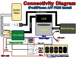
Audio/Video iPod/iPhone Integration in your FX
w/ Kuda Base, Dice Cradle, Dice MediaBridge, and NavTV
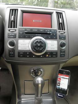
THIS GUIDE WILL DESCRIBE HOW TO INTEGRATE YOUR i-DEVICE (iPod/iPhone/iPad) INTO YOUR INFINITI FX WITH AUDIO/VIDEO OUTPUT WHILE MAINTAINING DEVICE CONTROL AND TEXT READOUT THROUGH YOUR FACTORY RADIO SCREEN. AT THE TIME OF THIS POSTING, THIS IS CURRENTLY THE ONLY WAY TO DO BOTH.
First, let me start off with a brief explanation of the Apple Authentication Chip that makes this whole project such a headache. We can all agree that the ideal result would be getting video out of the iPhone while maintaining text readout and track control on the factory radio, right? Apparently not that simple, thank you Apple.
The Apple Authentication Chip in the video cables utilizes 4 connections to the dock connector: Serial Rx, Serial Tx, 3.3v, and GND. It effectively terminates the Serial TTL lines allowing no other devices to communicate with the iPhone. It is undetermined how often the phone checks for the chip, but it is 100% confirmed that the video output will not open without it.
It also kills any chance of you using a device like the OEM front kit or USA spec (or GROM and any of the other cheap brands) from controlling the iPhone. All of these devices simply translate the iPhone's Serial commands to ones that the Infiniti radio understands since the Infiniti appears to use some form of Serial communication too. I will soon find out if it's TTL or RS232. The traffic from the Auth Chip blocks anything else from communicating right now.
So for the above reasons, the only viable options to get Audio AND Video out of your i-device simultaneously are through USB or Bluetooth A2DP streaming. I don’t want another Bluetooth device in my car that will just add clutter and render the existing Bluetooth buttons useless. The ultimate goal to make this work is to separate device control to the USB Data lines and free up the Serial Data lines to authenticate the video output.
If you have a 2009+ FX, you already have a USB port on your radio, so you’re set. Just buy an Apple A/V cable with USB (or any cable with the Apple Authorized Chipset) and it will plug and play to your radio with video for your NavTV device. The analog R/L audio cables remain unused.
If you have an 03-08 FX, continue reading because this is the only current way to integrate an iPod/iPhone/iPad with Video output while maintaining Digital Audio Out, Device Control thru the Radio, and Text Display on the Radio. Currently the only device to do this is the Dice MediaBridge MBR-1503-NIS (released mid-2011).
~~~~~~~~~~
Big Ticket Items:
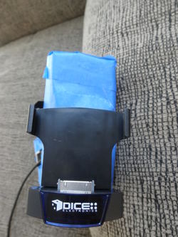
-Dice MediaBridge MBR-1503-NIS (currently $220 on Amazon)
-Dice G2 Cradle of your choice, I used DCR-50 (currently $50 on Amazon)
-Kuda Mounting Base (currently $73 from Kuda)
-PAC VCI-NIS or NavTool or NavTV (VCI currently $217 on Amazon)
-iPhone Composite A/V cable w/ USB, must contain Apple Authentication Chip (currently $20 at www.spider-foot.com)
(*sidenote – the Dice DCR-150 cradle claims to eliminates the need for an Apple A/V cable, however this is unconfirmed so I used a DCR-50 in this How-To)
Preparation (Kuda Base & Cradle):
1) Switch out the DICE G2 cradle post for the longer one. You will need this for proper cable clearance. Also prepare the face of the Kuda Base with painter’s tape. Pre-drilling is recommended here, as this will give you a cleaner hole in the faux-leather.
2) Mount your device to the cradle and find a symmetrical center point side-to-side. Top-to-bottom, you will need to eyeball a good center point that looks aesthetically pleasing with your particular device. Just mounting the DICE G2 cradle dead center will cause your device to stick up beyond the footprint of the Kuda Base. This is all a matter of preference and eyeballing. Once you have the positioning that you want, hold the cradle firmly to the Kuda Base and mark the 4 screw holes with pencil.

3) Proceed to pre-drill the 4 holes with a bit smaller than the screws to be used. The Kuda Base is made of fiberglass and simply screwing into it may crack the material. Remove the painter’s tape and gently secure the cradle to the Kuda Base with the supplied screws. I recommend orienting the rectangular DICE G2 cradle base such that the larger square holes are on the bottom, this will be come more apparent in Step 4. Don’t crank it down yet because it will need to be removed again.
(pic coming)
4) If you choose not to cut your A/V cable and run it through the Kuda Base as I have, skip to Step 5 (you will have to find an alternate solution for cable management).
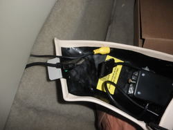
If you want to be able to rotate your device to horizontal, you need to decide right now if you will be rotating it right or left for the purposes of running the dock cable. I chose to rotate left, so I drilled a hole where the bottom right square hole in the G2 cradle base matches up with the Kuda Base. Use a pencil to make a fine dot in the 4 corners of this square. Remove the G2 cradle from the Kuda Base. Use an Exacto knife to cut the top layer of the faux-leather of the Kuda Base. I cut an “X” from dot to dot, folded back and taped the resulting triangles of fabric, and drilled my hole for the cable in the underlying layers. This allows a polished look on the exterior.
5) Re-attach the DICE G2 cradle, snugly this time. Set aside the base for installation later.
If you opted to cut your A/V cable, run your A/V cable through the hole in the base and reconnect the wires pin-to-pin on the back side. Give yourself long wire leads to work with. The smallest heat shrink tubing is recommended as these tiny wires are too delicate for electrical tape. This will all be hidden anyways, so while sound cable structure is important, it doesn’t have to be beautiful.

Bonus Content (the following is no longer applicable to this installation, so skip to the 2nd post if you wish):
I went a little more in depth because this was still an experiment and I was figuring it out as I went. I built my own A/V cable to try and use to pull out the video signal and pass-through the 30pin dock connector to the USA Spec PA15-NIS, which proved a futile effort as the 1[SUP]st[/SUP] page describes. Here is that process for those interested.
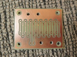
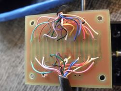
1) Build a 16pin circuit board, or have one etched. This will be used to pass all signals in the Ridax Dock Extension Cable through to the female connector.

2) Using a Radio Shack project box, drill holes on each of the longer sides for the cable in and out. Install grommets for strain relief. Run the wire already installed in the Kuda Base and the other half that you cut off in the Kuda Mount Preparation Step 4 section into either side of the box. Strip the cable end and strip just the tips of all the wires inside of it. Tin all of the ends with solder. Start attaching them pin-by-pin to the circuit board, making sure that the Composite Video and Video GND signals are accessible to be tapped into. My circuit board had extra traces built for this.

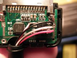
3) Open up the male dock connector of the iPhone A/V cable you wish to cannibalize and tap 4 wires to the Auth Chip as illustrated. The colors in the Ridax Dock Extension Cable that I have at the time of this write-up are as follows: Pink (3.3v), Black (GND), White (Serial Tx), Red (Serial Rx). Solder the other ends of these wires into the matching circuit board pins to tap the signal and the Apple Chip will authorize the video output to the RCA jack.

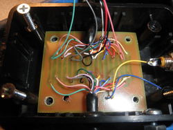
4) Install the circuit board into the box, solder side down. Drill a hole on one of the short ends of the box and install a panel mount RCA jack. Wire the Composite Video signal to the center, and Video Ground to the outer shield.

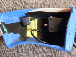
5) Screw on the lid to the Project Box and install the assembly into the Kuda Base with double-stick adhesive

[TABLE="align: center"]
[TR]
[TD]Need for Scosche Auth Chip[/TD]
[TD]Ridax Extension Wire Colors[/TD]
[TD]Pin[/TD]
[TD]Signal[/TD]
[TD]Description[/TD]
[/TR]
[TR]
[TD][/TD]
[TD]Blue[/TD]
[TD]1[/TD]
[TD]GND[/TD]
[TD]Ground (-), internally connected with Pin 2 on iPod motherboard[/TD]
[/TR]
[TR]
[TD][/TD]
[TD]N/C[/TD]
[TD]2[/TD]
[TD]GND[/TD]
[TD]Audio & Video ground (-), internally connected with Pin 1 on iPod motherboard[/TD]
[/TR]
[TR]
[TD][/TD]
[TD]Violet[/TD]
[TD]3[/TD]
[TD]Right[/TD]
[TD]Line Out - R (+) (Audio output, right channel)[/TD]
[/TR]
[TR]
[TD][/TD]
[TD]Lt Yellow[/TD]
[TD]4[/TD]
[TD]Left[/TD]
[TD]Line Out - L(+) (Audio output, left channel)[/TD]
[/TR]
[TR]
[TD][/TD]
[TD]N/C[/TD]
[TD]5[/TD]
[TD]Right In[/TD]
[TD]Line In - R (+)[/TD]
[/TR]
[TR]
[TD][/TD]
[TD]N/C[/TD]
[TD]6[/TD]
[TD]Left In[/TD]
[TD]Line In - L (+)[/TD]
[/TR]
[TR]
[TD][/TD]
[TD]Orange[/TD]
[TD]7[/TD]
[TD]Remote Sense[/TD]
[TD][/TD]
[/TR]
[TR]
[TD][/TD]
[TD]Lt Blue[/TD]
[TD]8[/TD]
[TD]Video Out[/TD]
[TD]Composite video output (only when slideshow active on iPod Photo)
or Component Video Pb[/TD]
[/TR]
[TR]
[TD][/TD]
[TD]N/C[/TD]
[TD]9[/TD]
[TD]S-Video Chrominance output[/TD]
[TD]for iPod Color, Photo only
or Component Video Y[/TD]
[/TR]
[TR]
[TD][/TD]
[TD]N/C[/TD]
[TD]10[/TD]
[TD]S-Video Luminance output[/TD]
[TD]for iPod Color, Photo only
or Component Video Pr[/TD]
[/TR]
[TR]
[TD][/TD]
[TD]Yellow[/TD]
[TD]11[/TD]
[TD]AUDIO_SW[/TD]
[TD]If connected to GND the iPhone sends audio signals through pin 3-4, otherwise it uses onboard speaker.[/TD]
[/TR]
[TR]
[TD]YES[/TD]
[TD]White[/TD]
[TD]12[/TD]
[TD]Tx[/TD]
[TD]ipod sending line, Serial TxD[/TD]
[/TR]
[TR]
[TD]YES[/TD]
[TD]Red[/TD]
[TD]13[/TD]
[TD]Rx[/TD]
[TD]ipod receiving line, Serial RxD[/TD]
[/TR]
[TR]
[TD][/TD]
[TD]N/C[/TD]
[TD]14[/TD]
[TD]RSVD[/TD]
[TD]Reserved[/TD]
[/TR]
[TR]
[TD][/TD]
[TD]N/C[/TD]
[TD]15[/TD]
[TD]GND[/TD]
[TD]Ground (-), internally connected with pin 16 on iPod motherboard[/TD]
[/TR]
[TR]
[TD]YES[/TD]
[TD]Black[/TD]
[TD]16[/TD]
[TD]GND[/TD]
[TD]USB GND (-), internally connected with pin 15 on iPod motherboard[/TD]
[/TR]
[TR]
[TD][/TD]
[TD]N/C[/TD]
[TD]17[/TD]
[TD]RSVD[/TD]
[TD]Reserved[/TD]
[/TR]
[TR]
[TD]YES[/TD]
[TD]Pink[/TD]
[TD]18[/TD]
[TD]3.3V[/TD]
[TD]3.3V Power (+)
Stepped up to provide +5 VDC to USB on iPod Camera Connector. If iPod is put to sleep while Camera Connector is present, +5 VDC at this pin slowly drains back to 0 VDC.[/TD]
[/TR]
[TR]
[TD][/TD]
[TD]Brown[/TD]
[TD]19[/TD]
[TD]+12V[/TD]
[TD]Firewire Power 12 VDC (+)[/TD]
[/TR]
[TR]
[TD][/TD]
[TD]Tan[/TD]
[TD]20[/TD]
[TD]+12V[/TD]
[TD]Firewire Power 12 VDC (+)[/TD]
[/TR]
[TR]
[TD]YES[/TD]
[TD]Lt Green[/TD]
[TD]21[/TD]
[TD]Accessory Indicator/Serial enable[/TD]
[TD]Different resistances indicate accessory type:
1kOhm - iPod docking station, beeps when connected
10kOhm - Takes some iPods into photo import mode
6.8 kΩ - Serial port mode. Pin 11-13 are TTL level. Requires MAX232 chip to convert to RS232 levels.
68kOhm - makes iPhone 3g send audio through line-out without any messages
500kOhm - related to serial communication / used to enable serial communications Used in Dension Ice Link Plus car interface
1MOhm - Belkin auto adaptor, iPod shuts down automatically when power disconnected Connecting pin 21 to ground with a 1MOhm resistor does stop the ipod when power (i.e. Firewire-12V) is cut. Looks to be that when this pin is grounded it closes a switch so that on loss of power the Ipod shuts off. Dock has the same Resistor.[/TD]
[/TR]
[TR]
[TD][/TD]
[TD]N/C[/TD]
[TD]22[/TD]
[TD]TPA (-)[/TD]
[TD]FireWire Data TPA (-)[/TD]
[/TR]
[TR]
[TD][/TD]
[TD]Lt Violet[/TD]
[TD]23[/TD]
[TD]5 VDC (+)[/TD]
[TD]USB Power 5 VDC (+)[/TD]
[/TR]
[TR]
[TD][/TD]
[TD]N/C[/TD]
[TD]24[/TD]
[TD]TPA (+)[/TD]
[TD]FireWire Data TPA (+)[/TD]
[/TR]
[TR]
[TD][/TD]
[TD]Green[/TD]
[TD]25[/TD]
[TD]Data (-)[/TD]
[TD]USB Data (-)[/TD]
[/TR]
[TR]
[TD][/TD]
[TD]N/C[/TD]
[TD]26[/TD]
[TD]TPB (-)[/TD]
[TD]FireWire Data TPB (-)[/TD]
[/TR]
[TR]
[TD][/TD]
[TD]Gray[/TD]
[TD]27[/TD]
[TD]Data (+)[/TD]
[TD]USB Data (+)
Pins 25 and 27 may be used in different manner. To force the iPod 5G to charge in any case, when USB Power 5 VDC (pin 23) is fed, 25 must be connected to 5V through a 10kOhm resistor, and 27 must be connected to the Ground (for example: pin 1) with a 10kOhm resistor.
iPod 5G can also be forced to charge by attaching the data + and the data - pins to the 5v via a 10k Ohm resistor ( BOTH PINS) and connecting pin 16 to the 5v (ground). (Confirmed working with iPod 5G 20GB). This provides 500mA of current for charging. For quicker charing, up to 1A, see below.
To charge an iPhone, 3G, 3GS, 4 / iPod Touch, 2nd gen, 3rd, 4th or Ipod Classic (6th Gen), usb data- (25) should be at 2.8v, usb data+(27) should be at 2.0v. This can be done with a few simple resistors: 33k to +5v (23) and 22k to gnd(16) to obtain 2v and 33k to +5v and 47k to gnd to obtain 2.8v. This is a notification to the iphone that it is connected to the external charger and may drain amps from the usb.
To charge iPod Nano pins 25 and 27 should be tied together and then connected to a 10K ohm resistor, and the other side of this resistors then needs to be connected to 5v power.
It's also possible to charge the iPod's or iPhone's battery to make use the of internal +3.3v output (18) terminal to connect the USB Data + (27) thru a 47k ohms resistor and the USB Data- (25) thru a 47k resistor to the USB Power source +5v (23). This way the USB function is still useable for normal operations and makes it easier the fit in a plug. The resistors are not to critical 2x 150k's still work.[/TD]
[/TR]
[TR]
[TD][/TD]
[TD]N/C[/TD]
[TD]28[/TD]
[TD]TPB (+)[/TD]
[TD]FireWire Data TPB (+)[/TD]
[/TR]
[TR]
[TD][/TD]
[TD]N/C[/TD]
[TD]29,30[/TD]
[TD]GND[/TD]
[TD]FireWire Ground (-)[/TD]
[/TR]
[/TABLE]
Back side of dock connector;
2 4 6 8 10 12 14 16 18 20 22 24 26 28 30
1 3 5 7 9 11 13 15 17 19 21 23 25 27 29
Pins 1,2 connected on motherboard.
Pins 15,16 connected on motherboard.
Pins 19,20 connected on motherboard.
Pins 29,30 connected on motherboard.
If you disassemble the original apple-ipod-dock-connector-cable and look at the connector itself, on the back side, where it is soldered, you can see the number 1 and 30 (e.g. pin 1 and 30). In this description NUMBERING is INVERSED: pin 1 is pin 30 and pin 29 is pin 2, so, don't look at numbers on connector.
~~~~~~~~~~
HOW-TO:
Audio/Video iPod/iPhone Integration in your FX
w/ Kuda Base, Dice Cradle, Dice MediaBridge, and NavTV
THIS GUIDE WILL DESCRIBE HOW TO INTEGRATE YOUR i-DEVICE (iPod/iPhone/iPad) INTO YOUR INFINITI FX WITH AUDIO/VIDEO OUTPUT WHILE MAINTAINING DEVICE CONTROL AND TEXT READOUT THROUGH YOUR FACTORY RADIO SCREEN. AT THE TIME OF THIS POSTING, THIS IS CURRENTLY THE ONLY WAY TO DO BOTH.
First, let me start off with a brief explanation of the Apple Authentication Chip that makes this whole project such a headache. We can all agree that the ideal result would be getting video out of the iPhone while maintaining text readout and track control on the factory radio, right? Apparently not that simple, thank you Apple.
The Apple Authentication Chip in the video cables utilizes 4 connections to the dock connector: Serial Rx, Serial Tx, 3.3v, and GND. It effectively terminates the Serial TTL lines allowing no other devices to communicate with the iPhone. It is undetermined how often the phone checks for the chip, but it is 100% confirmed that the video output will not open without it.
It also kills any chance of you using a device like the OEM front kit or USA spec (or GROM and any of the other cheap brands) from controlling the iPhone. All of these devices simply translate the iPhone's Serial commands to ones that the Infiniti radio understands since the Infiniti appears to use some form of Serial communication too. I will soon find out if it's TTL or RS232. The traffic from the Auth Chip blocks anything else from communicating right now.
So for the above reasons, the only viable options to get Audio AND Video out of your i-device simultaneously are through USB or Bluetooth A2DP streaming. I don’t want another Bluetooth device in my car that will just add clutter and render the existing Bluetooth buttons useless. The ultimate goal to make this work is to separate device control to the USB Data lines and free up the Serial Data lines to authenticate the video output.
If you have a 2009+ FX, you already have a USB port on your radio, so you’re set. Just buy an Apple A/V cable with USB (or any cable with the Apple Authorized Chipset) and it will plug and play to your radio with video for your NavTV device. The analog R/L audio cables remain unused.
If you have an 03-08 FX, continue reading because this is the only current way to integrate an iPod/iPhone/iPad with Video output while maintaining Digital Audio Out, Device Control thru the Radio, and Text Display on the Radio. Currently the only device to do this is the Dice MediaBridge MBR-1503-NIS (released mid-2011).
~~~~~~~~~~
Big Ticket Items:
-Dice MediaBridge MBR-1503-NIS (currently $220 on Amazon)
-Dice G2 Cradle of your choice, I used DCR-50 (currently $50 on Amazon)
-Kuda Mounting Base (currently $73 from Kuda)
-PAC VCI-NIS or NavTool or NavTV (VCI currently $217 on Amazon)
-iPhone Composite A/V cable w/ USB, must contain Apple Authentication Chip (currently $20 at www.spider-foot.com)
(*sidenote – the Dice DCR-150 cradle claims to eliminates the need for an Apple A/V cable, however this is unconfirmed so I used a DCR-50 in this How-To)
Preparation (Kuda Base & Cradle):
1) Switch out the DICE G2 cradle post for the longer one. You will need this for proper cable clearance. Also prepare the face of the Kuda Base with painter’s tape. Pre-drilling is recommended here, as this will give you a cleaner hole in the faux-leather.
2) Mount your device to the cradle and find a symmetrical center point side-to-side. Top-to-bottom, you will need to eyeball a good center point that looks aesthetically pleasing with your particular device. Just mounting the DICE G2 cradle dead center will cause your device to stick up beyond the footprint of the Kuda Base. This is all a matter of preference and eyeballing. Once you have the positioning that you want, hold the cradle firmly to the Kuda Base and mark the 4 screw holes with pencil.
3) Proceed to pre-drill the 4 holes with a bit smaller than the screws to be used. The Kuda Base is made of fiberglass and simply screwing into it may crack the material. Remove the painter’s tape and gently secure the cradle to the Kuda Base with the supplied screws. I recommend orienting the rectangular DICE G2 cradle base such that the larger square holes are on the bottom, this will be come more apparent in Step 4. Don’t crank it down yet because it will need to be removed again.
(pic coming)
4) If you choose not to cut your A/V cable and run it through the Kuda Base as I have, skip to Step 5 (you will have to find an alternate solution for cable management).
If you want to be able to rotate your device to horizontal, you need to decide right now if you will be rotating it right or left for the purposes of running the dock cable. I chose to rotate left, so I drilled a hole where the bottom right square hole in the G2 cradle base matches up with the Kuda Base. Use a pencil to make a fine dot in the 4 corners of this square. Remove the G2 cradle from the Kuda Base. Use an Exacto knife to cut the top layer of the faux-leather of the Kuda Base. I cut an “X” from dot to dot, folded back and taped the resulting triangles of fabric, and drilled my hole for the cable in the underlying layers. This allows a polished look on the exterior.
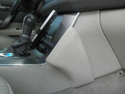
5) Re-attach the DICE G2 cradle, snugly this time. Set aside the base for installation later.
If you opted to cut your A/V cable, run your A/V cable through the hole in the base and reconnect the wires pin-to-pin on the back side. Give yourself long wire leads to work with. The smallest heat shrink tubing is recommended as these tiny wires are too delicate for electrical tape. This will all be hidden anyways, so while sound cable structure is important, it doesn’t have to be beautiful.
Bonus Content (the following is no longer applicable to this installation, so skip to the 2nd post if you wish):
I went a little more in depth because this was still an experiment and I was figuring it out as I went. I built my own A/V cable to try and use to pull out the video signal and pass-through the 30pin dock connector to the USA Spec PA15-NIS, which proved a futile effort as the 1[SUP]st[/SUP] page describes. Here is that process for those interested.
1) Build a 16pin circuit board, or have one etched. This will be used to pass all signals in the Ridax Dock Extension Cable through to the female connector.
2) Using a Radio Shack project box, drill holes on each of the longer sides for the cable in and out. Install grommets for strain relief. Run the wire already installed in the Kuda Base and the other half that you cut off in the Kuda Mount Preparation Step 4 section into either side of the box. Strip the cable end and strip just the tips of all the wires inside of it. Tin all of the ends with solder. Start attaching them pin-by-pin to the circuit board, making sure that the Composite Video and Video GND signals are accessible to be tapped into. My circuit board had extra traces built for this.
3) Open up the male dock connector of the iPhone A/V cable you wish to cannibalize and tap 4 wires to the Auth Chip as illustrated. The colors in the Ridax Dock Extension Cable that I have at the time of this write-up are as follows: Pink (3.3v), Black (GND), White (Serial Tx), Red (Serial Rx). Solder the other ends of these wires into the matching circuit board pins to tap the signal and the Apple Chip will authorize the video output to the RCA jack.
4) Install the circuit board into the box, solder side down. Drill a hole on one of the short ends of the box and install a panel mount RCA jack. Wire the Composite Video signal to the center, and Video Ground to the outer shield.
5) Screw on the lid to the Project Box and install the assembly into the Kuda Base with double-stick adhesive
iPhone/iPod Dock Connector Pinout
(w/ Ridax Extension Cable colors for reference)
(w/ Ridax Extension Cable colors for reference)
[TABLE="align: center"]
[TR]
[TD]Need for Scosche Auth Chip[/TD]
[TD]Ridax Extension Wire Colors[/TD]
[TD]Pin[/TD]
[TD]Signal[/TD]
[TD]Description[/TD]
[/TR]
[TR]
[TD][/TD]
[TD]Blue[/TD]
[TD]1[/TD]
[TD]GND[/TD]
[TD]Ground (-), internally connected with Pin 2 on iPod motherboard[/TD]
[/TR]
[TR]
[TD][/TD]
[TD]N/C[/TD]
[TD]2[/TD]
[TD]GND[/TD]
[TD]Audio & Video ground (-), internally connected with Pin 1 on iPod motherboard[/TD]
[/TR]
[TR]
[TD][/TD]
[TD]Violet[/TD]
[TD]3[/TD]
[TD]Right[/TD]
[TD]Line Out - R (+) (Audio output, right channel)[/TD]
[/TR]
[TR]
[TD][/TD]
[TD]Lt Yellow[/TD]
[TD]4[/TD]
[TD]Left[/TD]
[TD]Line Out - L(+) (Audio output, left channel)[/TD]
[/TR]
[TR]
[TD][/TD]
[TD]N/C[/TD]
[TD]5[/TD]
[TD]Right In[/TD]
[TD]Line In - R (+)[/TD]
[/TR]
[TR]
[TD][/TD]
[TD]N/C[/TD]
[TD]6[/TD]
[TD]Left In[/TD]
[TD]Line In - L (+)[/TD]
[/TR]
[TR]
[TD][/TD]
[TD]Orange[/TD]
[TD]7[/TD]
[TD]Remote Sense[/TD]
[TD][/TD]
[/TR]
[TR]
[TD][/TD]
[TD]Lt Blue[/TD]
[TD]8[/TD]
[TD]Video Out[/TD]
[TD]Composite video output (only when slideshow active on iPod Photo)
or Component Video Pb[/TD]
[/TR]
[TR]
[TD][/TD]
[TD]N/C[/TD]
[TD]9[/TD]
[TD]S-Video Chrominance output[/TD]
[TD]for iPod Color, Photo only
or Component Video Y[/TD]
[/TR]
[TR]
[TD][/TD]
[TD]N/C[/TD]
[TD]10[/TD]
[TD]S-Video Luminance output[/TD]
[TD]for iPod Color, Photo only
or Component Video Pr[/TD]
[/TR]
[TR]
[TD][/TD]
[TD]Yellow[/TD]
[TD]11[/TD]
[TD]AUDIO_SW[/TD]
[TD]If connected to GND the iPhone sends audio signals through pin 3-4, otherwise it uses onboard speaker.[/TD]
[/TR]
[TR]
[TD]YES[/TD]
[TD]White[/TD]
[TD]12[/TD]
[TD]Tx[/TD]
[TD]ipod sending line, Serial TxD[/TD]
[/TR]
[TR]
[TD]YES[/TD]
[TD]Red[/TD]
[TD]13[/TD]
[TD]Rx[/TD]
[TD]ipod receiving line, Serial RxD[/TD]
[/TR]
[TR]
[TD][/TD]
[TD]N/C[/TD]
[TD]14[/TD]
[TD]RSVD[/TD]
[TD]Reserved[/TD]
[/TR]
[TR]
[TD][/TD]
[TD]N/C[/TD]
[TD]15[/TD]
[TD]GND[/TD]
[TD]Ground (-), internally connected with pin 16 on iPod motherboard[/TD]
[/TR]
[TR]
[TD]YES[/TD]
[TD]Black[/TD]
[TD]16[/TD]
[TD]GND[/TD]
[TD]USB GND (-), internally connected with pin 15 on iPod motherboard[/TD]
[/TR]
[TR]
[TD][/TD]
[TD]N/C[/TD]
[TD]17[/TD]
[TD]RSVD[/TD]
[TD]Reserved[/TD]
[/TR]
[TR]
[TD]YES[/TD]
[TD]Pink[/TD]
[TD]18[/TD]
[TD]3.3V[/TD]
[TD]3.3V Power (+)
Stepped up to provide +5 VDC to USB on iPod Camera Connector. If iPod is put to sleep while Camera Connector is present, +5 VDC at this pin slowly drains back to 0 VDC.[/TD]
[/TR]
[TR]
[TD][/TD]
[TD]Brown[/TD]
[TD]19[/TD]
[TD]+12V[/TD]
[TD]Firewire Power 12 VDC (+)[/TD]
[/TR]
[TR]
[TD][/TD]
[TD]Tan[/TD]
[TD]20[/TD]
[TD]+12V[/TD]
[TD]Firewire Power 12 VDC (+)[/TD]
[/TR]
[TR]
[TD]YES[/TD]
[TD]Lt Green[/TD]
[TD]21[/TD]
[TD]Accessory Indicator/Serial enable[/TD]
[TD]Different resistances indicate accessory type:
1kOhm - iPod docking station, beeps when connected
10kOhm - Takes some iPods into photo import mode
6.8 kΩ - Serial port mode. Pin 11-13 are TTL level. Requires MAX232 chip to convert to RS232 levels.
68kOhm - makes iPhone 3g send audio through line-out without any messages
500kOhm - related to serial communication / used to enable serial communications Used in Dension Ice Link Plus car interface
1MOhm - Belkin auto adaptor, iPod shuts down automatically when power disconnected Connecting pin 21 to ground with a 1MOhm resistor does stop the ipod when power (i.e. Firewire-12V) is cut. Looks to be that when this pin is grounded it closes a switch so that on loss of power the Ipod shuts off. Dock has the same Resistor.[/TD]
[/TR]
[TR]
[TD][/TD]
[TD]N/C[/TD]
[TD]22[/TD]
[TD]TPA (-)[/TD]
[TD]FireWire Data TPA (-)[/TD]
[/TR]
[TR]
[TD][/TD]
[TD]Lt Violet[/TD]
[TD]23[/TD]
[TD]5 VDC (+)[/TD]
[TD]USB Power 5 VDC (+)[/TD]
[/TR]
[TR]
[TD][/TD]
[TD]N/C[/TD]
[TD]24[/TD]
[TD]TPA (+)[/TD]
[TD]FireWire Data TPA (+)[/TD]
[/TR]
[TR]
[TD][/TD]
[TD]Green[/TD]
[TD]25[/TD]
[TD]Data (-)[/TD]
[TD]USB Data (-)[/TD]
[/TR]
[TR]
[TD][/TD]
[TD]N/C[/TD]
[TD]26[/TD]
[TD]TPB (-)[/TD]
[TD]FireWire Data TPB (-)[/TD]
[/TR]
[TR]
[TD][/TD]
[TD]Gray[/TD]
[TD]27[/TD]
[TD]Data (+)[/TD]
[TD]USB Data (+)
Pins 25 and 27 may be used in different manner. To force the iPod 5G to charge in any case, when USB Power 5 VDC (pin 23) is fed, 25 must be connected to 5V through a 10kOhm resistor, and 27 must be connected to the Ground (for example: pin 1) with a 10kOhm resistor.
iPod 5G can also be forced to charge by attaching the data + and the data - pins to the 5v via a 10k Ohm resistor ( BOTH PINS) and connecting pin 16 to the 5v (ground). (Confirmed working with iPod 5G 20GB). This provides 500mA of current for charging. For quicker charing, up to 1A, see below.
To charge an iPhone, 3G, 3GS, 4 / iPod Touch, 2nd gen, 3rd, 4th or Ipod Classic (6th Gen), usb data- (25) should be at 2.8v, usb data+(27) should be at 2.0v. This can be done with a few simple resistors: 33k to +5v (23) and 22k to gnd(16) to obtain 2v and 33k to +5v and 47k to gnd to obtain 2.8v. This is a notification to the iphone that it is connected to the external charger and may drain amps from the usb.
To charge iPod Nano pins 25 and 27 should be tied together and then connected to a 10K ohm resistor, and the other side of this resistors then needs to be connected to 5v power.
It's also possible to charge the iPod's or iPhone's battery to make use the of internal +3.3v output (18) terminal to connect the USB Data + (27) thru a 47k ohms resistor and the USB Data- (25) thru a 47k resistor to the USB Power source +5v (23). This way the USB function is still useable for normal operations and makes it easier the fit in a plug. The resistors are not to critical 2x 150k's still work.[/TD]
[/TR]
[TR]
[TD][/TD]
[TD]N/C[/TD]
[TD]28[/TD]
[TD]TPB (+)[/TD]
[TD]FireWire Data TPB (+)[/TD]
[/TR]
[TR]
[TD][/TD]
[TD]N/C[/TD]
[TD]29,30[/TD]
[TD]GND[/TD]
[TD]FireWire Ground (-)[/TD]
[/TR]
[/TABLE]
Back side of dock connector;
2 4 6 8 10 12 14 16 18 20 22 24 26 28 30
1 3 5 7 9 11 13 15 17 19 21 23 25 27 29
Pins 1,2 connected on motherboard.
Pins 15,16 connected on motherboard.
Pins 19,20 connected on motherboard.
Pins 29,30 connected on motherboard.
If you disassemble the original apple-ipod-dock-connector-cable and look at the connector itself, on the back side, where it is soldered, you can see the number 1 and 30 (e.g. pin 1 and 30). In this description NUMBERING is INVERSED: pin 1 is pin 30 and pin 29 is pin 2, so, don't look at numbers on connector.
Attachments
Last edited:


")