- Location
- Portland, OR
Update:
So, I've progressed into differential calculus in my quest for the perfect intake. :nerd: I fully remember how little I enjoyed fluid dynamics the first time around. Ironic that I would need to use it for something seemingly as simple as designing an air intake system. Apparently most aftermarket intakes have very little engineering involved in their design due to the complexity of the issue. That's not to say that aftermarket intakes don't work. Trial and error is a very effective tool especially if you have a flow bench and a dyno machine handy. Regardless, here are some of the highlights from my research thus far and some ideas I'm tossing around.
Research & calculations: (I'll try to spare you the formulas and jargon.)
1. The VQ35DE displaces 213.58cu in.
2. At 7000rpms, assuming 100% Volumetric efficiency (usually not the case) it is capable of consuming 432.36CFM.
3. The K&N cone filter that comes with the Stillen CAI is not sufficient to support this flow rate without restricting flow when it's perfectly clean and oiled, let alone when it's old and dirty.
4. The K&N drop in filter does not even meet the minimum flow requirements for 7K rpms at 85% Ve, which is a much more realistic operating efficiency for a stock FX engine at redline. Again, assuming it's brand new and perfectly oiled.
4. Volumetric efficiency (Ve) can in fact exceed 100% and often does in high performance NA motors due to the momentum of the air in the intake tract which pressurizes the combustion chamber. Ve almost always exceeds 100% in FI applications.
5. Cylinder head design is a black art that involves voodoo and chicken bones.
6. Plug your ears Dave; both laminar and turbulent flow exists in the intake tract, and in way more places than I can address. Luckily, the effects of these are minimal enough that I'm going to disregard.
Some ideas: (I've broken this project into three parts; Before the filter, the airbox, and after the filter. Right now I'm working on the portion I call "after the filter" which is between the lower plenum and the airbox.)
1. Increasing the internal diameter and/or reducing the length of the "z-tube". The former would require a revised 3.5" MAF sensor tube, the fairly extensive modification of the velocity stack, and the procurement of a new (larger or possibly odd shaped) filter. The latter would only require a new mounting bracket and possibly a new cylindrical filter that is longer and smaller in diameter than my current cone filter.
2. Incrementally staggering the internal diameter of the intake tube. This one requires a LONG explanation that I'm not up to right now.
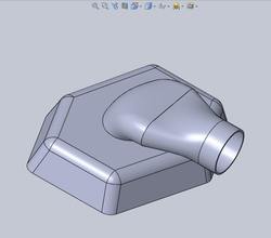
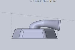
3. Modifying the upper plenum from its current "back and to the right" inlet to a more logical and symmetrical "front and center" inlet configuration. This would facilitate a very short and simple intake tract that utilizes the existing air inlets above the radiator. In this case I would have to model a new upper plenum and have it built somewhere. I would also have to relocate the throttle body and everything to which it is attached. A slight bonus is that the MAF sensor wires will still reach.
Random question: Does anyone know how much clearance exists between the top of the stock plenum and the bottom of the closed hood? Preferably at the front of the plenum?
I have more but I need to go make dinner. I'll post another update soon.
So, I've progressed into differential calculus in my quest for the perfect intake. :nerd: I fully remember how little I enjoyed fluid dynamics the first time around. Ironic that I would need to use it for something seemingly as simple as designing an air intake system. Apparently most aftermarket intakes have very little engineering involved in their design due to the complexity of the issue. That's not to say that aftermarket intakes don't work. Trial and error is a very effective tool especially if you have a flow bench and a dyno machine handy. Regardless, here are some of the highlights from my research thus far and some ideas I'm tossing around.
Research & calculations: (I'll try to spare you the formulas and jargon.)
1. The VQ35DE displaces 213.58cu in.
2. At 7000rpms, assuming 100% Volumetric efficiency (usually not the case) it is capable of consuming 432.36CFM.
3. The K&N cone filter that comes with the Stillen CAI is not sufficient to support this flow rate without restricting flow when it's perfectly clean and oiled, let alone when it's old and dirty.
4. The K&N drop in filter does not even meet the minimum flow requirements for 7K rpms at 85% Ve, which is a much more realistic operating efficiency for a stock FX engine at redline. Again, assuming it's brand new and perfectly oiled.
4. Volumetric efficiency (Ve) can in fact exceed 100% and often does in high performance NA motors due to the momentum of the air in the intake tract which pressurizes the combustion chamber. Ve almost always exceeds 100% in FI applications.
5. Cylinder head design is a black art that involves voodoo and chicken bones.
6. Plug your ears Dave; both laminar and turbulent flow exists in the intake tract, and in way more places than I can address. Luckily, the effects of these are minimal enough that I'm going to disregard.
Some ideas: (I've broken this project into three parts; Before the filter, the airbox, and after the filter. Right now I'm working on the portion I call "after the filter" which is between the lower plenum and the airbox.)
1. Increasing the internal diameter and/or reducing the length of the "z-tube". The former would require a revised 3.5" MAF sensor tube, the fairly extensive modification of the velocity stack, and the procurement of a new (larger or possibly odd shaped) filter. The latter would only require a new mounting bracket and possibly a new cylindrical filter that is longer and smaller in diameter than my current cone filter.
2. Incrementally staggering the internal diameter of the intake tube. This one requires a LONG explanation that I'm not up to right now.
3. Modifying the upper plenum from its current "back and to the right" inlet to a more logical and symmetrical "front and center" inlet configuration. This would facilitate a very short and simple intake tract that utilizes the existing air inlets above the radiator. In this case I would have to model a new upper plenum and have it built somewhere. I would also have to relocate the throttle body and everything to which it is attached. A slight bonus is that the MAF sensor wires will still reach.
Random question: Does anyone know how much clearance exists between the top of the stock plenum and the bottom of the closed hood? Preferably at the front of the plenum?
I have more but I need to go make dinner. I'll post another update soon.