FX50 Intake Mod

FQ50s

Member
Car
Fx50s
Name
Shaun
I know that there are no official intakes for the 5.0L V8 for our cars and those that have attempted havent had good results. Well, Im going to attempt it a little differently. I procurred older G35 MAF guess what, they fit perfectly! I will be getting some MAF adapters next to fit dual 3” AEM Dryflow intakes will utilizing the stock front snorkel. Here’s a pic of me test fitting the maf....
 

Attachments

  • E880262B-B5A3-44F0-A1AA-441F2744B26F.jpeg
    E880262B-B5A3-44F0-A1AA-441F2744B26F.jpeg
    190.6 KB · Views: 1,107
  • D5F12ABA-8C5A-4CD3-B3E6-79358B3D655B.jpeg
    D5F12ABA-8C5A-4CD3-B3E6-79358B3D655B.jpeg
    216.1 KB · Views: 1,132
Ok git all the parts in today and installed everything:

Parts needed:
- x2 g35 (08’) or g37 mafs (about $25 each)
- x2 g35 3” intake MAF adapters (about $10 each)
- star bits
- flathead aNd philips screwdriver
- 10mm socket and ratchet
- 2x 3” flange conical intake (recommend AEM Dryflow), get 6-8inches in length
 

Attachments

  • 40FE5062-7F55-4338-8430-E226ACE892A0.jpeg
    40FE5062-7F55-4338-8430-E226ACE892A0.jpeg
    125.1 KB · Views: 358
Last edited:
Installation is pretty easy:

- start out by removing all the engine covers. They’re held on by push in plastic clips

- next, remove the intakes from each side by unclipping the MAF, loosening the throttle body hose, and unbolting the side bolts holding them down. Yank it up afterwards with a little force and they’ll pop off

- start prepping ur g35 MAFs by removing the MAF sensor (they’re held on by 2 star bolts). You’ll want to remove ur stick MAF sensor and clean it with MAF cleaner as well.

- place on MAF adapter and tighten things up with bolt, washer, and nut.

- put on the conical intake and the MAF adapter and tighten up clamp. Make sure it is in the right direction (sensor towards intake side).

- place the entire intake assembly on engine bay and finaggle it into the throttle body hose and tighten up the hose clamp

- now connect up the MaF wiring harness to the MAF and screw them down tight

- place back on all engine covers for a stealthy look
 

Attachments

  • D75FA414-8D27-4825-83AE-F21B5587AAE0.jpeg
    D75FA414-8D27-4825-83AE-F21B5587AAE0.jpeg
    172.2 KB · Views: 951
  • F8118D99-F963-4731-A2DB-6C20D45F04E2.png
    F8118D99-F963-4731-A2DB-6C20D45F04E2.png
    88.5 KB · Views: 920
  • 452EB0BD-C34F-4B8C-93AF-BEE52078BD1E.jpeg
    452EB0BD-C34F-4B8C-93AF-BEE52078BD1E.jpeg
    181.8 KB · Views: 917
  • B2A89108-744C-44B1-8206-A475FB7F55C2.jpeg
    B2A89108-744C-44B1-8206-A475FB7F55C2.jpeg
    167.3 KB · Views: 1,044
  • C8DACC7C-1EFC-4254-9B5A-CF4C8B991811.jpeg
    C8DACC7C-1EFC-4254-9B5A-CF4C8B991811.jpeg
    167.6 KB · Views: 1,068
  • 5272E849-605D-4441-A197-017BAD521991.jpeg
    5272E849-605D-4441-A197-017BAD521991.jpeg
    133.3 KB · Views: 1,060
Last edited:
Driving impressions:

- power : loss if a little torque down low (typical aftermarket intake characteristic). However up top there is a noticeable gain as it rushes to redline vert quickly

- sound : at full WOT, sounds vicious with my borla exhaust

Overall, Im happy with it. Like the increase in power up top. Has a very OE look to it and want sifficult to install.
 
You should’ve recorded a before and after video so that we could heck out the difference! Good job in the mod man.
 
Sounds dopee. Love the growl up top. If only you could fit a Stillen G3 on a 50...


Sent from my iPhone
 
I'd put the stock intake boxes back on with the cone filter for the best result. Even with the ducts there you're sucking in more hot air than before. Nice job on the DIY and figuring it all out though
 
I'd put the stock intake boxes back on with the cone filter for the best result. Even with the ducts there you're sucking in more hot air than before. Nice job on the DIY and figuring it all out though

Is that what you did? Do you have pics? What are your IATs? Would love to see what others have done....
 
^^^ Nice job. Thats the correct and only way a cold air intake should be done on the FX.


Sent from my iPhone
 
Nicely done! I assume this is all custom? Any reason why you didn't go with silicone hoses or tempered paint in the engine bay?
 
If I may point out for your benefit 3 things that are holding the performance of your intakes back.
1. Length; the longer the pipe the greater the pressure loss.
2. Bends; More bends and the greater the degree, the greater the pressure loss.
3. One might think the shields might be beneficial in some way but the open portion of the filter is close to and facing a heat source while the shield is blocking positive pressure and much cooler air. These shields are also preventing 50% of the filter from efficiently drawing in air as they sit so close to it. The intake will have to fight for air at idle when the fans are pulling air through the radiator to cool it down.
The diameter of the pipe could be larger but without software to tune for a larger MAF housing, you're sol. If that fx50 were mine, I'd remove the 45* bends and the blue silicone couplers and then reinstall the filters. I see you have a performance device so you can test the difference between both. Your iat's will suffer but I believe you will get noticeably better performance regardless and if you do, cut those pipes down as short as possible for more power.
Sorry for my english. I have to use google translator.
I copied the design of this intake from here. Stillen’s Gen 3 Nissan 370Z Air Intake, Tested! > MotoIQ - Automotive Tech, Project Cars, Performance & Motorsports
there you can see the test on the dyno. unfortunately without shields you can not ride in the rain. The filter becomes wet. The difference in temperature compared with the regular system is -10 -15C( obd2 logs from maf) The pressure drop from the bends is compensated by the larger area of the filter surface and their design. the diameter of the branch pipe in the area of the maf is the same as the nominal.
 

Attachments

  • 41d990as-960.jpg
    41d990as-960.jpg
    141.3 KB · Views: 245
Last edited:
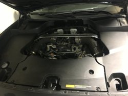
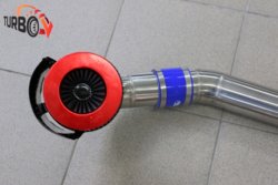
Your english is fine V. I see the heat shield doesn't wrap the filter as much as I thought it did. That's good. With your V8 and dual intake/throttle body set up, more power is available to you. I made 8hp/5tq on my intake, V6 with single throttle body. Not to argue but in no way can the air filters compensate for pipe length or diameter. If you have aftermarket software for your ecu you can go with larger diameter pipes along with a larger diameter MAF housing which makes a big difference. The intakes look great. If you remove the 90* bends as I mentioned above and you don't notice a significant difference, I'll fly to Russia and you can kick me in the nutz:rofl:. Big fan of Buteyko and Frolov!

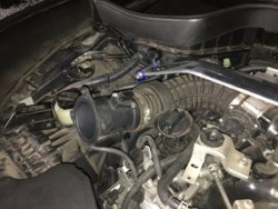
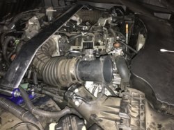
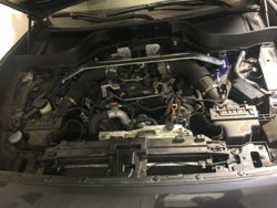
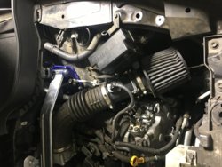
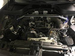
Below is a quote from my thread which is the best I've found regarding this topic. If you dig around my thread (the link below) you'll see where I added length and a 90* bend to get my filter out of the bay and what it did to performance. Killed it. You might not be affected as negatively because you're engine draws air from 2 pipes. You might've gotten a nice bump just because the oem units suck so much ass whereas my negative experience with more pipe and bends was AFTER I tuned for the large diameter short pipe. The difference was night and day.
FX35 - onthemove MOD's

"Here's some down and dirty regarding the effects of intake length and size. Found this while researching "lowest pressure drop designs". A written explanation of why elongating AND introducing a 90* bend in my pipe just to get the filter lower and out of the bay failed so miserably. The power loss was so dramatic I felt it right away and there was no doubt in my mind I fucked up.

Easy Performance | CAI System Design Consideration Primer

" What this means is going from a 4 inch duct to a 3 inch ID duct increases the friction losses by ~2.7 times. Thus, it is not hard to see that a 4 inch duct is preferable over a 3 inch duct by reducing friction losses as well as lowering the air velocity by nearly half. "

" If a 90° bend is designed into the intake duct, then the following can be estimated as shown in the following table. In these examples, 3" and 4 " ID pipes are given. For these pipe sizes, the centerline radius of close 90° elbows are typically equivalent to the diameter of the pipe.
easy-performance-cai-eq-lenght-table-jpg.jpg
These calculations illustrate the addition of a single 90° bend in a 3-inch or 4-inch duct is the same as adding 48 inches or 64 inches of straight duct respectively in its place. When compared to the rather short length desired for the intake duct, adding a single bend has a dramatic affect on increasing the intake's resistance to airflow. For bends other than 90°, they can be estimated by multiplying the 90° bend resistance by a percentage factor. For a 45° bend, the total friction loss is about 65% of the 90° bend's resistance. For a 180° bend, the total friction loss is about 140% of the 90° bend's resistance.
From the above table, one might conclude that the 48 inch equivalent length given by a 3 inch ID pipe would provide less friction than the 64 inch equivalent length for a 4 inch ID pipe. However, one must now determine the friction that is produced by these two pipe sizes before making such a judgment. As shown earlier, the 3 inch pipe has 2.69 times more friction than a 4 inch pipe. If you calculate the equivalent length of 4 inch ID pipe that would have the same friction as the 90° bend in a 3 inch ID pipe, then you would need to multiply the 48 inch equivalent length by 2.69. This result tells us the 90° bend in a 3 inch pipe is equivalent to 119 inches of 4 inch ID straight pipe. Thus, having bends and smaller pipe diameter is detrimental towards producing good flow characteristics in an induction system."

" Materials that have high reflectivity coefficients are primarily metals and of those, copper, silver, gold and aluminum are among the highest. All of these metals have reflectivity coefficients above 0.96. This means they reflect more than 96% of all the thermal radiation that strikes their surface. For the construction of induction systems, aluminum tends to be a good material of choice. Plastics and other organic materials tend to be very poor at reflecting radiant heat. The reflectivity coefficients of plastics and rubbers tend to be below 0.06. This means plastics only reflect less than 6% of all the thermal radiation that strikes their surface. This means over 94% of the radiant heat is absorbed by the plastics or rubbers. Consequently, they are undesirable materials when exposed to radiant heat. "

" Summation
When considering how to design an optimal induction system for a particular vehicle, all of the design aspects discussed earlier as well as other characteristics must be given careful consideration. Restricting the design considerations to the aspects discussed above, some basic design conclusions can be listed.
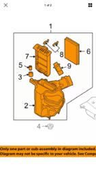
  • Select a high flow surface impingement style filter element
  • Use as large a filter element as practical for the application
  • Position the filter so the least amount of dirt and debris will be entering the filter
  • Maintenance the filter regularly to maintain optimal performance
  • Use as large of an intake duct as practical to connect the filter element to the engine
  • Intake duct's interior surface should be as smooth as possible
  • Avoid rapid changes in diameters/cross-sectional areas through the induction system
  • Avoid or limit the bends needed in the induction system
  • Keep the intake track to the engine as short as possible
  • The induction system should draw 100% of its air from outside the engine bay or where minimally higher than ambient air temperature regions exist
  • All induction component surfaces that are exposed to higher temperature components and surfaces should be made of highly thermal reflective materials
  • All surfaces that come in contact with the intake air should be insulated from all potential heat sources "
 
Last edited:
Back
Top