Disclaimer: Use this DIY at your own risk, as I will not be responsible for any problems this DIY may cause.
This DIY will guide you through the installation of a KP Technologies MX20 Controller Module to run the fog lights independent of the headlights.
You will need a KP Technologies MX20 Controller Module (http://www.kptechnologies.com/products.php#/12) and your regular hand tools such as metric sockets set, wire cuter & striper, electrical tape, soldering iron and hear shrink tube if you chose to use them to complete this DIY. It will take approximately 2 - 3 hours at leisure pace.
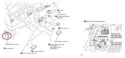
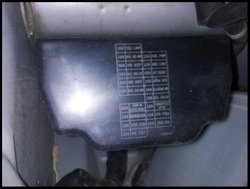
1. Remove trimmings in the driver foot well to gain access to the BCM. The following pictures show the BCM location.

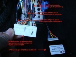
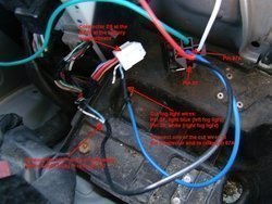
2. There are 3 connectors located on the BCM. The one we need to tab into is the biggest connector, M3 (40 pin connector). Disconnect the M3 connector and make 3 connections at the connector wires.

3. Ground the KP module black wire to nearby bare metal.
4. Route the KP module orange wire through the firewall to the battery compartment in the engine bay.
5. Reinstall the trimmings.
6. Remove the battery compartment cover and the cowl top cover.
7. Remove the battery from the compartment.
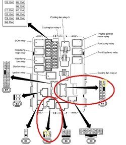
8. Remove the IPDM cover by pulling it straight up.

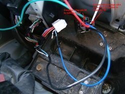
9. The E8 & E5 connectors are the ones you will be making connections.

10. Reach to the back top edge of the IPDM and unclip two tabs to release the IPDM from its mounting bracket to create some slack in the wires.
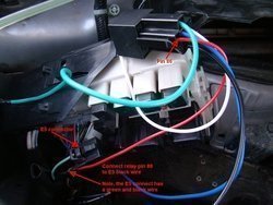
11. You will be cutting 2 wires and making 3 connections at the IPDM. Using the provided relay that comes with the KP module, make the following connections.
Note: The wire color of your relay pigtail may have different color. Just follow the pin # to make the connections.
Disconnect the E8 connector and wire the relay pigtail as in the picture. Reconnect the E8 connector when completed the wiring.

12. Disconnect the E5 connector and wire the relay pigtail as in the picture. Reconnect the E5 connector when completed the wiring.

13. Make the following relay connections as in the picture.

14. Reinstall the battery and test the installation.

16. Reinstall IPDM cover, cowl top cover and batter compartment cover.

This DIY will guide you through the installation of a KP Technologies MX20 Controller Module to run the fog lights independent of the headlights.
You will need a KP Technologies MX20 Controller Module (http://www.kptechnologies.com/products.php#/12) and your regular hand tools such as metric sockets set, wire cuter & striper, electrical tape, soldering iron and hear shrink tube if you chose to use them to complete this DIY. It will take approximately 2 - 3 hours at leisure pace.
1. Remove trimmings in the driver foot well to gain access to the BCM. The following pictures show the BCM location.
2. There are 3 connectors located on the BCM. The one we need to tab into is the biggest connector, M3 (40 pin connector). Disconnect the M3 connector and make 3 connections at the connector wires.
3. Ground the KP module black wire to nearby bare metal.
4. Route the KP module orange wire through the firewall to the battery compartment in the engine bay.
5. Reinstall the trimmings.
6. Remove the battery compartment cover and the cowl top cover.
7. Remove the battery from the compartment.
8. Remove the IPDM cover by pulling it straight up.
9. The E8 & E5 connectors are the ones you will be making connections.
10. Reach to the back top edge of the IPDM and unclip two tabs to release the IPDM from its mounting bracket to create some slack in the wires.
11. You will be cutting 2 wires and making 3 connections at the IPDM. Using the provided relay that comes with the KP module, make the following connections.
Note: The wire color of your relay pigtail may have different color. Just follow the pin # to make the connections.
Disconnect the E8 connector and wire the relay pigtail as in the picture. Reconnect the E8 connector when completed the wiring.
12. Disconnect the E5 connector and wire the relay pigtail as in the picture. Reconnect the E5 connector when completed the wiring.
13. Make the following relay connections as in the picture.
14. Reinstall the battery and test the installation.
16. Reinstall IPDM cover, cowl top cover and batter compartment cover.
Attachments
-
 BCM3.jpg77.6 KB · Views: 293
 -
 DSC00345_S.jpg160.1 KB · Views: 178
 -
 DSC00350_S.jpg209.7 KB · Views: 170
 -
 IPDM2.jpg59 KB · Views: 125
 -
 IPDM1.jpg67.9 KB · Views: 136
 -
 DSC00352_S.jpg176.3 KB · Views: 146
 -
 handyandy_thejackchanofmechanics-eyes.png5 KB · Views: 161
 -
 DSC00355.jpg158.5 KB · Views: 155
 -
 DSC00350_S2.jpg187.8 KB · Views: 145
")