
SteadiFX
Member
- Location
- Orlando, FL
HOW-TO:
Amplify bass to your factory Bose subwoofer
w/ a simple DIY circuit using RadioShack parts
I have taken bits and pieces from guides on other forums and info in this forum to assemble into a single How-To specific to the FX. I did not invent this technique, but I am using it in my vehicle with much success.
Supplies (RadioShack catalog #’s):
-Dual General-Purpose IC PC Board (#276-159) - $2.19
-8-pin IC Socket (#276-1995) - $0.59
-LM741CN Operational Amplifier 8-pin Dip (#276-007) - $1.19
-500-piece ¼-watt Carbon-Film Resistor Assortment (#271-312) - $9.99
*note – we need only the 4.7k ohm and 15k ohm resistors, the 15k is not sold alone however
-1.0µF 50V 20% Axial-Lead Non-Polarized Elect. Capacitor (#272-996) - $1.29
-100µF 50V 20% Radial-lead Electrolytic Capacitor (#272-1044) - $1.49
-Project Enclosure 3x2x1" (#270-1801) - $2.69
-Assorted Grommets 31-pack (#64-3025) - $2.29
-Spare 24awg wire of various colors
-Some small PC case screws to secure circuit board to project box
-Soldering iron
-Solder (60/40 makeup recommended)
Principle:
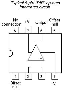
An Operational Amplifier like the LM741 we will use here is being used to obtain Gain or Amplification. For a gain of +2dB, the two resistors on the inverting input would be Equal Value. In our application it will be 4.7k to 15k, which yields +3.19dB gain. The gain of the OP-AMP is determined by the ratio of the 4.7k ohm resistor and the 15k resistor. Some people feel as if the bass is boosted too much by this circuit and opt to use a 6.0k ohm resistor instead (the closer the ratio is to being Equal, the less gain). Here is how the internals of the LM741 are mapped out.

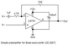
The FX sends Woofer(+) and Woofer(-) to a module in the spare tire well that runs both subwoofers. We want to pass the Woofer(+) signal through our amplifier and tap the Woofer(-) signal for reference. Here is the circuit we are trying to construct:

Preparation:
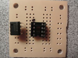
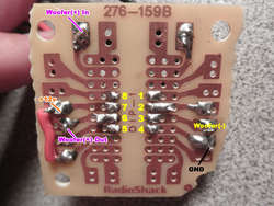
1) Solder the 8-pin IC Socket to the center of the PC Board. Pick a top-left corner to reference and make a dot with a sharpie as pictured. Pin 1 on the chip is denoted by the recessed dot. Pin numbering goes in a counter-clockwise direction. Leave the chip disconnected while you solder.

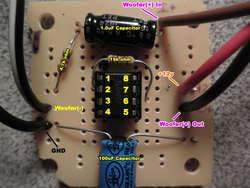
2) Add the components pin-for-pin as pictured. The solder side is provided with pin numbers as reference. Use the pin numbers on the diagram above as reference if needed. All remaining components are bi-directional EXCEPT for the 100uF Capacitor. It has a designated (-) side noted on its casing.

On the solder side, notice the small section of wire bridging 2 pins. For space reasons, we do this to connect the 100uF capacitor to Pin 7, while keeping it out of the way on the PC board.

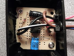
3) Drill holes in the Project Enclosure for the Vinyl Grommets, keeping in mind the height of the circuit board once installed. I separated the Power/GND wires from the rest to keep things straight during installation. Mount the board in the Project Enclosure, BEFORE installing Vinyl Grommets for clearance. I had to shave down the board slightly to fit. Run wires through the Grommets and strain relief with zip ties. Screw on the lid.

Installation:
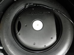
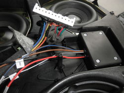
1) Open the hatch and lift the spare tire well cover to expose the Bose Subwoofer. Remove the center tie down and remove subwoofer. Use a ¼” Socket to remove all 9 bolts holding the subwoofer cover. Remove the cover and unplug the vehicle harness that connects to the subwoofer enclosure.

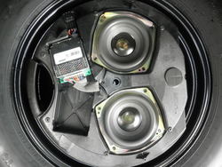
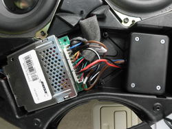
2) Now would be a good time to put some double-stick adhesive on the bottom of the Project Enclosure and stick it in the available space. I butted mine up against the plastic posts and put double-stick on the side to stick to one of the walls. Remove the Woofer Module pictured below and unplug the connector.

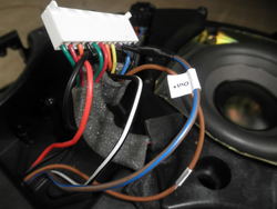
3) Peel apart some of the foam tape to expose the wires between the module harness and the harness that connects to the car. Make your connections to the factory harness as follows:
+12v: Tap Orange wire
Ground: Tap Black wire
Woofer(+) In: Cut Violet wire, connect to vehicle side of Violet wire
Woofer(+) Out: Connect to Woofer Module side of Violet wire
Woofer(-): Tap Yellow wire


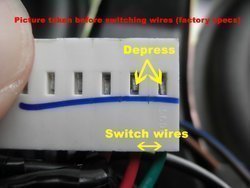
4) Reverse the phase of the woofers by switching the Red/Green wires for each pair. Do this by depressing the metal tab in the picture and pulling the wire out of the connector. When you are done, Red should be where Green was and vise-versa for both pairs on the connector.

5) Plug in Module, reinstall. Plug vehicle harness back into Bose Subwoofer. Reinstall subwoofer cover, secure Bose Subwoofer to spare tire well with the center tie down. Replace tire well cover. Turn on vehicle and enjoy.

Attachments
-
 LM741.png4.2 KB · Views: 1,354
 -
 subpreamp.jpg10 KB · Views: 902
 -
 P9080455.jpg70.6 KB · Views: 1,019
 -
 boardfrontweb-1.jpg69.2 KB · Views: 860
 -
 soldersideweb.jpg78.4 KB · Views: 805
 -
 P9080462.jpg94.7 KB · Views: 1,553
 -
 P9090469.jpg118 KB · Views: 1,715
 -
 P9090470.jpg174.9 KB · Views: 8,789
 -
 P9090471.jpg110.4 KB · Views: 3,561
 -
 P9090475.jpg69.1 KB · Views: 5,818
 -
 moduleconnectorweb-1.jpg43.8 KB · Views: 886
 -
 P9090477.jpg146.9 KB · Views: 10,906
Last edited:
