tchuck's custom intake

that location has been tested in the past by others I think & it seemed to have less airflow than up top, measured power loss on the dyno acording to those who tried I think. it will work great though if you open up a nice size scoop to that area, otherwise it'll have less white air than even where it is now. even taking the fog light out would only help so much but would be a start, you;d need to pressurize that cavity while enclosing it to make any kind of possitive improvement. my air filters will go similar to that left & right but ducts will have to be built in too
 
Update:

As any of you who have read through this thread know, I have had quite a lot of opposition from quite a few knowledgeable folks in regard to my plans to design (or rather redesign) an upper plenum for my 35. Well, I'm no fool and as Kat Williams says "if everybody in yo life says you smokin' crack, mutha%$&ka you are probably smokin crack!". That's not a direct quote but you get the idea. Anyway, I've decided to heed some of this advice and put my plenum project on the back burner for the time being and continue my research. I've been reading a lot about the subject lately from any source I can find, and have learned a great deal about the intricacies of engine design. My plenum design has changed several times since the last model I showed you guys and it will probably change again before I show you another. Suffice it to say the next iteration will be astonishing... Well, maybe not astonishing but a little better at least. :wink:
That brings me to the rest of my imaginary intake system, which is how I keep myself busy between work, marriage, and "study sessions". This includes a revised air box, intake tube, and filter location. At this point my strategy has been to create the different options I come up with, and use my very limited range of equipment to conduct rudimentary comparisons. When I narrow the field to a few promising contenders, I'll try some more sophisticated comparative methods. Currently, I think what I'm doing is sufficient to weed out the bad apples. I've modeled a couple different intake tube ideas and run them on the "virtual flow bench", used a vacuum gauge on the intake manifold to compare resistance, performed about 15 pedal dance ECU resets, and logged some hard miles on my butt-dyno. :laugh:
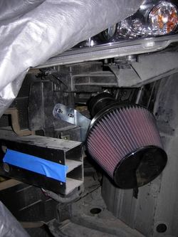
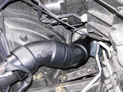
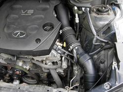
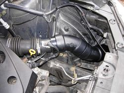
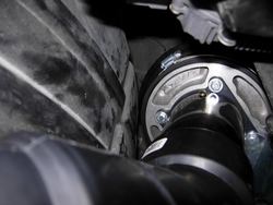
The picture I posted above is the most recent and I think my favorite filter location thus far. I got the idea from poking around under the hood of my Audi, in which the air box sits directly atop the inner fender liner. A common mod for increased air flow in that circumstance is to drill holes through the bottom of the air box and down through the fender liner, effectively opening the air box to the outside world directly. The picture is showing the fitment test in which the filter is just hanging from a wire. It's mounted now and in a slightly different place. Here's a newer pic:
newfilterlocation2.jpg
Possibilities for this location include a fairly simple heat shield, air scoops from the skid plate and from the opening below the grill, full isolation, a larger filter, adding venting to the fender liner, or any combination thereof.

Oh yeah, and I have a new addition to the "which mods do you regret" thread that I'm sure you will find entertaining... Hopefully I'll get to posting that tonight.

Comments? Questions? Suggestions? This process has "hardened my skin" a bit so to speak so good or bad, bring it on. :laugh:

nice, do you plan on sealing off this area?

The tentative plan is to finish up the piping tomorrow and see how it goes. So far I can tell that this area has three major benefits over the existing, and one drawback. The benefits are that a significantly larger (in diameter and length) filter will fit here, it's much more conducive to isolation if I decide to go that route, and it's quite a bit further from the heat source. The drawback (aside from turbo's observation below) is that the intake tract is gaining two extra bends and about 14" of length. I am dealing with that by slightly increasing the internal diameter of the excess intake piping.

that location has been tested in the past by others I think & it seemed to have less airflow than up top, measured power loss on the dyno acording to those who tried I think. it will work great though if you open up a nice size scoop to that area, otherwise it'll have less white air than even where it is now. even taking the fog light out would only help so much but would be a start, you;d need to pressurize that cavity while enclosing it to make any kind of possitive improvement. my air filters will go similar to that left & right but ducts will have to be built in too

That's disappointing. I couldn't find anything about anyone routing their filter there in an FX... Do you happen to remember any details? Maybe a keyword or something I could search for to find that thread (if it's a thread)? I suppose worst case scenario is I move it back up to the top. So far I've performed no irreversible work, aside from a slight trimming of my Stillen air box but that doesn't really affect anything but the fit.
 

Attachments

  • newfilterlocation2.jpg
    newfilterlocation2.jpg
    93.5 KB · Views: 51
  • newfilterlocation2.jpg
    newfilterlocation2.jpg
    93.5 KB · Views: 45
  • newfilterlocation2.jpg
    newfilterlocation2.jpg
    93.5 KB · Views: 39
  • newfilterlocation2.jpg
    newfilterlocation2.jpg
    93.5 KB · Views: 25
  • newfilterlocation2.jpg
    newfilterlocation2.jpg
    93.5 KB · Views: 28
  • newfilterlocation2.jpg
    newfilterlocation2.jpg
    93.5 KB · Views: 39
there was a big long thread on the injen & low end power loss too I think... the injen had it's own set of issues but there were a few guys who tried a lot of different intake stuff too back then... I remember specifically someone testing the filter lower & seeing loss but I searched around a bit & can't find much...
 
there was a big long thread on the injen & low end power loss too I think... the injen had it's own set of issues but there were a few guys who tried a lot of different intake stuff too back then... I remember specifically someone testing the filter lower & seeing loss but I searched around a bit & can't find much...

EDIT: My wife just told me that this post makes me sound like a bit of a jerk, so I'm slimming it down in the interest of simplicity...

I still can't find anything about moving the Stillen velocity stack and filter to the "Injen location". :frown:

However, I just spent the past hour and a half read through several of the Injen threads on the org. Suffice it to say I'm still pretty optimistic about this filter location.

For anyone interested...

Here's the first thread I could find about the intake:
http://shannon.v8eaters.com/viewtop...n&sid=32aca014639e17ccae02e3b6ab92e4bf#p14355

Here's Injen's introduction thread:
http://shannon.v8eaters.com/viewtop...sid=0469087a72c248c19a6a7cc519579d8c&start=25

Here's the thread started by the first guy to install said intake:
http://shannon.v8eaters.com/viewtop...it=injen&sid=f67a0877cf273c01a87011474d9dff3d

Here's the first of the G-Tech comparison results:
http://shannon.v8eaters.com/viewtop...it=injen&sid=32aca014639e17ccae02e3b6ab92e4bf

and another good one:
http://shannon.v8eaters.com/viewtop...it=injen&sid=c7a69a9e22a95999a8359be3e252ce84

Now, to finish the piping...

Double EDIT: The piping is done and I took the FX out for a test run a little earlier. I didn't get a chance to REALLY push it, but I did go WOT a few times at various rpm ranges. Bear in mind I did zero actual testing. These are just my thoughts after cruising around a bit. I had the full Stillen CAI w/ z-tube installed prior to this, so when I say "faster" or "louder", that is my reference point.

First impressions

1. Low end seems pretty unaffected aside from the increased volume.
2. Mid range might be slightly better, it's hard to say. Could be my imagination.
3. It feels significantly faster at high rpm (from 5K-6.5K).
4. It is shockingly loud! Very similar tonal characteristics to the Stillen CAI sans air box, but really much louder from 3K-6500 rpm.
5. The aluminum velocity stack and filter were literally cold to the touch after more than 40min of driving that included several WOT runs to the redline. It is about 58 degrees here right now with moderate humidity. This has not been the case for any of my other intake iterations. The Stillen CAI sans air box left the aluminum velocity stack so hot that I could only touch it for a second or two at a time.

This option is definitely staying on for a while. I'll take some pictures in the daylight tomorrow.
 
Last edited:
Here are some pics of the piping. It's just a prototype I built from 3" sch40 abs pipe. I think it's plumbing pipe technically. Anyway, I'm going to play around with it a bit more to get it to fit a little better, then decide on a material for the finalized version. I'm thinking aluminum for the lower sections (upstream of the MAF sensor) and a more heat soak resistant plastic for the half nearest the engine. Any thoughts?

Here are some pics:

This is the upper section. I did end up performing one irreversible modification when I sawed the flanged end off the MAF sensor tube. The idea there was to keep the sensor in the factory location and keep the flanged end on the velocity stack.
DSCN1914.jpg

Here is an overall view of the new pieces. You can see the less than perfect fit that I referred to earlier.
DSCN1915.jpg

Lower section.
DSCN1916.jpg

This one shows the flange from the MAF tube attached to the filter and mounting bracket. The bracket is the one that comes with the Stillen CAI kit, bent at an angle. The whole assembly is very sturdy as is, but like I said before, the pipe lengths need to massaged a little more. Also, you can't really tell from this pic, but the filter does not touch any part of the bodywork or fender liner. The smallest clearance is about 1/4", between the filter and the fender lining. It's about "9 o'clock" relative to the filter in this pic.
DSCN1917.jpg
 

Attachments

  • DSCN1914.jpg
    DSCN1914.jpg
    93.6 KB · Views: 66
  • DSCN1915.jpg
    DSCN1915.jpg
    104.7 KB · Views: 33
  • DSCN1917.jpg
    DSCN1917.jpg
    56.2 KB · Views: 41
  • DSCN1916.jpg
    DSCN1916.jpg
    108.6 KB · Views: 49
  • DSCN1914.jpg
    DSCN1914.jpg
    93.6 KB · Views: 46
  • DSCN1915.jpg
    DSCN1915.jpg
    104.7 KB · Views: 48
  • DSCN1916.jpg
    DSCN1916.jpg
    108.6 KB · Views: 31
  • DSCN1917.jpg
    DSCN1917.jpg
    56.2 KB · Views: 34
  • DSCN1914.jpg
    DSCN1914.jpg
    93.6 KB · Views: 36
  • DSCN1915.jpg
    DSCN1915.jpg
    104.7 KB · Views: 36
  • DSCN1916.jpg
    DSCN1916.jpg
    108.6 KB · Views: 69
  • DSCN1917.jpg
    DSCN1917.jpg
    56.2 KB · Views: 38
  • DSCN1914.jpg
    DSCN1914.jpg
    93.6 KB · Views: 33
  • DSCN1914.jpg
    DSCN1914.jpg
    93.6 KB · Views: 37
  • DSCN1915.jpg
    DSCN1915.jpg
    104.7 KB · Views: 35
  • DSCN1916.jpg
    DSCN1916.jpg
    108.6 KB · Views: 37
  • DSCN1917.jpg
    DSCN1917.jpg
    56.2 KB · Views: 35
  • DSCN1915.jpg
    DSCN1915.jpg
    104.7 KB · Views: 34
  • DSCN1916.jpg
    DSCN1916.jpg
    108.6 KB · Views: 38
  • DSCN1917.jpg
    DSCN1917.jpg
    56.2 KB · Views: 39
  • DSCN1914.jpg
    DSCN1914.jpg
    93.6 KB · Views: 37
  • DSCN1915.jpg
    DSCN1915.jpg
    104.7 KB · Views: 67
  • DSCN1916.jpg
    DSCN1916.jpg
    108.6 KB · Views: 37
  • DSCN1917.jpg
    DSCN1917.jpg
    56.2 KB · Views: 33
Of course going for a custom one piece tube from the Throttle Body to your filter would be best, but honestly what you have should work fine in terms of performance. The only minus in your current design would be all the joints/connections and I doubt it would impact your design negatively in a significant way. Totally understand if the look isn't up to your standard tho.

If you don't mind aluminum material, check out Spectre's website - they have generic intake tube components you can fit together in any configuration.

http://www.spectreperformance.com/#CATALOG

I spy a FX carbon grounding kit - nice!
 
Really enjoy looking at threads and images like this, keep going man. Any concerns re: moisture or is that area "tight"?
 
Of course going for a custom one piece tube from the Throttle Body to your filter would be best, but honestly what you have should work fine in terms of performance. The only minus in your current design would be all the joints/connections and I doubt it would impact your design negatively in a significant way. Totally understand if the look isn't up to your standard tho.

If you don't mind aluminum material, check out Spectre's website - they have generic intake tube components you can fit together in any configuration.

http://www.spectreperformance.com/#CATALOG

I spy a FX carbon grounding kit - nice!

It's not the look I dislike so much as the lack of a smooth air path and more appropriate material. I actually sort of like the industrial look of the rigid ABS fittings. I don't really know if it will make a difference, but the only reason I used ABS is because it's so readily available. It also seems to be resonating pretty severely at about 5200rpm, which is rather unpleasant. Seriously, the volume close to doubles around that area at WOT. It's really kind of shocking. Almost sounds like Vtech or something. :confused:

I like those Spectre tubes! Thanks!!! :tup:

You spy correctly. :biggrin: Speaking of which, can you direct me to a picture of the transmission grounding point? I couldn't find it in the development thread...

---------- Post added at 07:27 PM ---------- Previous post was at 07:16 PM ----------

Really enjoy looking at threads and images like this, keep going man. Any concerns re: moisture or is that area "tight"?


Thanks!
That's a good question. The area is fairly sealed with the exception of 1) the +/-2" hole in the skid plate directly under the filter, and 2) the 5 or so small vertical vents cut into the fender liner. Both of which are OEM. I can't imagine it's anything to be concerned with though considering the filter is soaked in oil and about 8" from either opening. I guess I'll find out soon though, the forecast shows rain starting Wednesday and continuing FOR-EH-VER... :tongue:
 
It's not the look I dislike so much as the lack of a smooth air path and more appropriate material. I actually sort of like the industrial look of the rigid ABS fittings. I don't really know if it will make a difference, but the only reason I used ABS is because it's so readily available. It also seems to be resonating pretty severely at about 5200rpm, which is rather unpleasant. Seriously, the volume close to doubles around that area at WOT. It's really kind of shocking. Almost sounds like Vtech or something. :confused:

I like those Spectre tubes! Thanks!!! :tup:

You spy correctly. :biggrin: Speaking of which, can you direct me to a picture of the transmission grounding point? I couldn't find it in the development thread...
Transmission grounding location:
///2839&postcount=6

As for the noise at WOT, hard to address without comparing to other FX intakes - might be totally normal. Mine was absolutely much louder after the intake, again after the spacer, and again after the exhaust. But only at WOT, which isn't really normal driving for me. Under normal acceleration, it sounds only marginally different than stock.

Perfect, thanks. I remember seeing that pic before but I couldn't find it.
 
update

Dudes, check this one out! This is almost exactly what my original idea was for the front fed plenum. Unfortunately after much research I've realized that even if I was capable of pulling off a design like this (probably not realistically) there is no way I could justify the expense of having one built. (sigh) So it goes... Either way this one is very cool.

http://www.cj-motorsports.com/catdefrontintake.htm

So I'm back to square one, sort of, which is designing an upper plenum that will fit onto the OEM DE lower plenum. My recently revised, less ambitious, and more realistic design goals are twofold; To provide equal airflow to all cylinders and to minimize alterations to all related components... The throttle body in particular, the relocation of which I've realized would to be a serious PITA.

In related news, I just ordered a couple sections of mandrel bent 3" polished aluminum tubing and a few silicone hump connectors for my custom intake system. I'm going to order a larger K&N filter and move my bracket down a bit so it will fit in it's current general location before I install the new pieces. That should be my next update.
 
Wow very cool! Still ALOT of money though I think id almost rather have the cosworth upper plenum just because it looks nice, and its half the price of this one. Any idea of added horsepower with this front intake unit?
 
thats huge

For real! The bottom half is machined from an aluminum block too... crazy. Definitely too much $$ for me.

... Any idea of added horsepower with this front intake unit?

Nope, I just found it last night.

i think this will look a lot nice if you can fit it on the bottom part of the bumper

http://www.ppsonline.net/airintake_FrontMount.htm

:k:


That one in particular is made for a +/- 1.8L motor so the piping is probably too small in diameter and certainly wont fit without drastic mods. I'm not in love with that filter either... Trying to stick with a K&N cone filter, which would never survive that location. I also measured 7" between the bumper and radiator in that area so any cone filter would have to be smaller than the one that comes with the Stillen CAI, which IMO is too small already.
 
Last edited:
That's a what I'm a talking about! That monster is super bad ass. Funny, he says "looks like Brandon's math with the iPhone level app worked..." I think he means the calculator, because the drawing he shows is from Solidworks and no iPhone is going to be doing solid modeling any time soon, especially not with Solidworks! :laugh: A little industry humor that made me chuckle...

UPDATE:

I haven't been able to spend much time on my intake project recently as work has been exceedingly demanding. My personal project list is getting uncomfortably long... (Sigh)

I found the down side to my current (in fender) filter location; Access. It is so difficult to get the filter out while the bumper is installed that any possible benefits are wholly negated. One way around this would be to use a smaller filter, but I actually want a larger filter, so I think this location is out, at least for the filter itself. I may end up routing an intake pipe down there from my airbox eventually, but that seems pretty far down the road. I'm going to move the filter back to it's original-ish location and focus my efforts on the plenum. Considering it will completely determine the shape and location of the filter, I can't justify devoting to it any more time than I already have.

I think I have finalized my plenum plan enough to start cutting. I've said it before but so far every time I look at it again I change my mind so at this point it is still in the "close to done" category. I'm going to revisit it again after lunch today. In essence, my upper plenum will be front fed, connected directly to the TB, then to my custom airbox containing a filter like THIS via the stock MAF sensor.

Questions for for you guys: I read somewhere that good practice for placement for the MAF sensor is "at least" 12 inches upstream of the TB in order to ensure laminar flow @ the sensor itself. Can anyone expound upon this principle? How exactly does this effect the function of the MAF sensor? I most definitely will not have 12" between the two...more like 4". Is this a deal breaker?
 
Back
Top