superwario
Member
- Car
- 2011 FX35 AWD
Hey guys,
I have been wanting to install a dash cam ever since I bought this car 3 years ago and finally had enough time to get this done. I would say the difficulty level is 2 out of 5 since this involves very minor soldering.
Since this is dealing with the car's electrical's I also have to add that I WILL DISCLAIM ALL INSTANCES OF MALFUNCTION TO YOUR CAR, DASH CAM, OR ANYTHING ELSE BY PERFORMING THIS MOD.
So without further ado, let's get to it!
Summary: What I am doing here is making my own pigtail wire tap in order to use the power that goes into the rearview mirror as a power source for my dash cam. This connection is exactly the same as those powertaps you see made for radar detectors, but much cheaper to make yourself. Also from my research they do not even make these power taps for dash cams.
Step 1: The first step is to gather the materials needed for this project. This will include:


Step 2: Insert the Heat shrink tubing into the wires, so that after we are done soldering we can move them up and shrink them into place with the heat-gun.

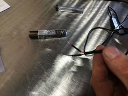
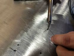
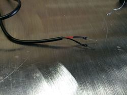
Step 3: Prime the ends of the header pins and the exposed wiring that came with your 12v to 5v USB converter with some solder. After priming, join the two parts together with the solder gun. Be patient!

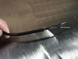
Step 4: Move the heat shrink tubing up into place and hit it with the heat gun so that it shrinks into place. I also put a larger piece of heat-shrink tubing around the whole thing to make sure everything looks nice and tidy. The caveat is that I had to make sure I knew which wire was red and which one was black, since the heat shrink tubing covered the colors up.


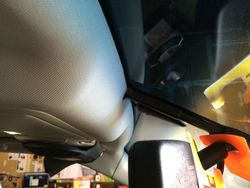
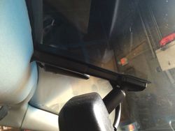
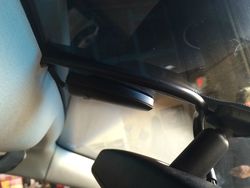
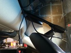
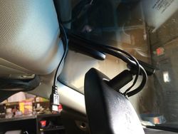
Step 5: Shove your newly soldered 12v to 5v converter wire into the headliner. I found the headliner is a little tighter in the middle but looser towards the passenger side, so I fed it into there and just slide the wires over to the middle. The wire hider for the rearview mirror comes off as well. Just slide the top part down and snap the bottom part off of the windshield connector. After that, you can route the wires down towards the connector and snap the wire hider back on. It's a tight fit, but it will fit in there.


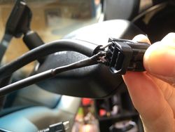
Step 6: Remove the connector from the back of the mirror and familiarize yourself with the wire colors. There are 3 wires: The Brown one is the switched 12v power, which means the power goes to it when the car is turned on. The Black is the Ground. TheGrey is the constant power which I didn't use. (Depending on if you want your camera always on, even when your car is off, then you might want to use this wire, but i didn't want to risk my car battery being run-down).

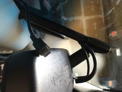
Step 7: Plug your Red (+) wire from your converter into the Brown connector and the Black (-) wire into the black connector. It should go in a with a pretty satisfying click. My header pins ended up sticking a little farther out then i intended so a cut a little bit off with wire clippers before sticking it back in.

Step 8: Plug back in the connector into the rearview mirror.


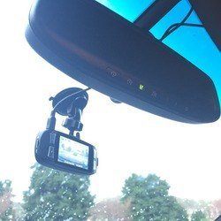
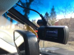
Step 9: Install your Dash Cam, plug it in, and enjoy!!!

I have been wanting to install a dash cam ever since I bought this car 3 years ago and finally had enough time to get this done. I would say the difficulty level is 2 out of 5 since this involves very minor soldering.
Since this is dealing with the car's electrical's I also have to add that I WILL DISCLAIM ALL INSTANCES OF MALFUNCTION TO YOUR CAR, DASH CAM, OR ANYTHING ELSE BY PERFORMING THIS MOD.
So without further ado, let's get to it!
Summary: What I am doing here is making my own pigtail wire tap in order to use the power that goes into the rearview mirror as a power source for my dash cam. This connection is exactly the same as those powertaps you see made for radar detectors, but much cheaper to make yourself. Also from my research they do not even make these power taps for dash cams.
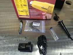
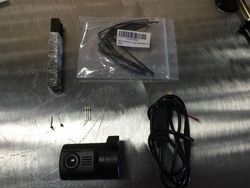
Step 1: The first step is to gather the materials needed for this project. This will include:
- Your Dash Cam
- A 12v to 5v USB connector; either micro-usb, mini-usb, or another connection depending on the dash cameras that you use (You can find these on ebay for cheap; also mine came with a built in power protection so I didn't buy an inline fuse for this project)
- Breakaway header pins (You only need two, I got mine on Amazon.com and it came with 150 of them for about $6 bucks
 )
) - Heat shrink tubing (To keep everything nice and tidy)
- Soldering iron and and solder material
- Heat gun
Step 2: Insert the Heat shrink tubing into the wires, so that after we are done soldering we can move them up and shrink them into place with the heat-gun.
Step 3: Prime the ends of the header pins and the exposed wiring that came with your 12v to 5v USB converter with some solder. After priming, join the two parts together with the solder gun. Be patient!
Step 4: Move the heat shrink tubing up into place and hit it with the heat gun so that it shrinks into place. I also put a larger piece of heat-shrink tubing around the whole thing to make sure everything looks nice and tidy. The caveat is that I had to make sure I knew which wire was red and which one was black, since the heat shrink tubing covered the colors up.
Step 5: Shove your newly soldered 12v to 5v converter wire into the headliner. I found the headliner is a little tighter in the middle but looser towards the passenger side, so I fed it into there and just slide the wires over to the middle. The wire hider for the rearview mirror comes off as well. Just slide the top part down and snap the bottom part off of the windshield connector. After that, you can route the wires down towards the connector and snap the wire hider back on. It's a tight fit, but it will fit in there.
Step 6: Remove the connector from the back of the mirror and familiarize yourself with the wire colors. There are 3 wires: The Brown one is the switched 12v power, which means the power goes to it when the car is turned on. The Black is the Ground. TheGrey is the constant power which I didn't use. (Depending on if you want your camera always on, even when your car is off, then you might want to use this wire, but i didn't want to risk my car battery being run-down).
Step 7: Plug your Red (+) wire from your converter into the Brown connector and the Black (-) wire into the black connector. It should go in a with a pretty satisfying click. My header pins ended up sticking a little farther out then i intended so a cut a little bit off with wire clippers before sticking it back in.
Step 8: Plug back in the connector into the rearview mirror.
Step 9: Install your Dash Cam, plug it in, and enjoy!!!
Attachments
-
 U2U7o0b.jpg167.8 KB · Views: 624
 -
 U2U7o0b.jpg167.8 KB · Views: 706
 -
 U2U7o0b.jpg167.8 KB · Views: 694
 -
 G4Yn3W3.jpg176.8 KB · Views: 865
 -
 G4Yn3W3.jpg176.8 KB · Views: 722
 -
 Tfpw7XE.jpg160.7 KB · Views: 735
 -
 G4Yn3W3.jpg176.8 KB · Views: 709
 -
 Tfpw7XE.jpg160.7 KB · Views: 709
 -
 Tfpw7XE.jpg160.7 KB · Views: 692
 -
 9OStqIQ.jpg183.9 KB · Views: 896
 -
 9OStqIQ.jpg183.9 KB · Views: 776
 -
 9OStqIQ.jpg183.9 KB · Views: 788
 -
 O4cjK7i.jpg156.9 KB · Views: 778
 -
 O4cjK7i.jpg156.9 KB · Views: 746
 -
 BpRttS9.jpg170.9 KB · Views: 870
 -
 O4cjK7i.jpg156.9 KB · Views: 737
 -
 BpRttS9.jpg170.9 KB · Views: 770
 -
 BpRttS9.jpg170.9 KB · Views: 756
 -
 u5tZfH2.jpg129.2 KB · Views: 742
 -
 u5tZfH2.jpg129.2 KB · Views: 700
 -
 u5tZfH2.jpg129.2 KB · Views: 743
 -
 rmwkpbh.jpg92 KB · Views: 804
 -
 rmwkpbh.jpg92 KB · Views: 766
 -
 rmwkpbh.jpg92 KB · Views: 728
 -
 l3LflIR.jpg95.1 KB · Views: 907
 -
 l3LflIR.jpg95.1 KB · Views: 735
 -
 l3LflIR.jpg95.1 KB · Views: 781
 -
 1PH0ElB.jpg124 KB · Views: 1,216
 -
 1PH0ElB.jpg124 KB · Views: 798
 -
 1PH0ElB.jpg124 KB · Views: 852
 -
 QLt1U0R.jpg88.8 KB · Views: 829
 -
 QLt1U0R.jpg88.8 KB · Views: 819
 -
 B4ZFZnf.jpg109.3 KB · Views: 3,009
 -
 QLt1U0R.jpg88.8 KB · Views: 824
 -
 B4ZFZnf.jpg109.3 KB · Views: 1,562
 -
 JfiebAy.jpg125.5 KB · Views: 1,656
 -
 B4ZFZnf.jpg109.3 KB · Views: 953
 -
 JfiebAy.jpg125.5 KB · Views: 898
 -
 JfiebAy.jpg125.5 KB · Views: 858
 -
 W7tE1gq.jpg113.1 KB · Views: 751
 -
 W7tE1gq.jpg113.1 KB · Views: 732
 -
 W7tE1gq.jpg113.1 KB · Views: 720
 -
 4PdSMxk.jpg109 KB · Views: 931
 -
 4PdSMxk.jpg109 KB · Views: 936
 -
 4PdSMxk.jpg109 KB · Views: 717