Alright guys, so here's the long awaited DIY write-up of Rex9271's custom made paddle shifter bracket installation
Available for the following Infiniti years and models:
EX / QX50 (2008 - 2014 model years)
FX / QX70 (2009 - 2014 model years)
IMPORTANT NOTES - READ FIRST!
NOTE 1: Steering column assembly must come with power tilt option.
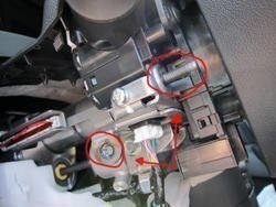
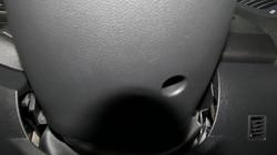
NOTE 2: Verify your steering column requires this bracket before purchase. Some production runs do come with the mounting points already present on the steering column. See figure A & B for visual reference.
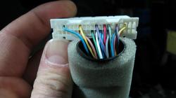
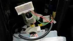
NOTE 3: Verify if the factory harness for the paddle shifters is present (See Fig C). Even with the factory mounting points, the wire harness may not be factory installed. Record shows 2009 year model has both.
NOTE 4: There has been production variations in the 2013 FX where some come with the factory mounting points while others come with a harness taped underneath the steering column. Verify your prior to ordering.
NOTE 5: Removing the steering wheel is not required and does not make the installation easier, just longer.
Step 1 - Verify bracket and wire harness requirements
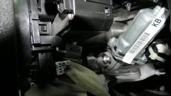
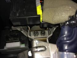
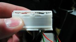
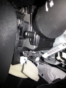
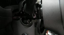
Fig A - Showing OEM paddle mounts, no bracket necessary (Wire harness may be required):
Steering column view - Left

Steering Column View - Right

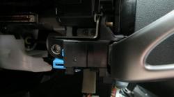
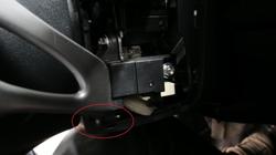
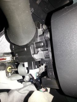
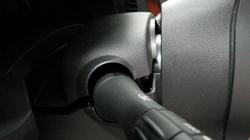
Fig B - Showing missing OEM paddle mounts and wire harness, REX9271's bracket and wire harness required:
Steering column view - Left

Steering column view - Right

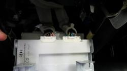
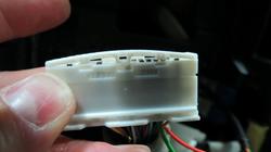
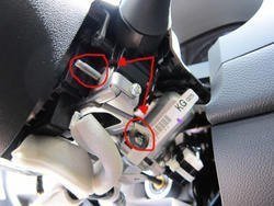
Fig C - Showing factory harness taped up underneath steering column ready for an easy plug-n-play setup

Step 2 - Required Parts
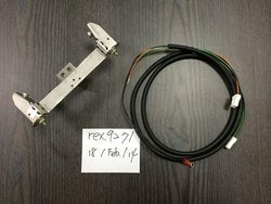
REX9271's Paddle Shifter Mount/Harness Kit
- REX9271's paddle shifter mount and wiring harness kit can be found in the Vendor's section
( https://www.infinitiscene.com/searc...le-Shifter-bracket-kit-for-EX-amp-2Gen-FX-115 )

Infiniti Paddles
- You can use a pair of paddle shifters from either a Nissan 370Z, Infiniti G35, G37 with the Infiniti/Nissan part number of 25549-JK0000 (Black leather on the paddles)
- Other colors are available such as stone or beige if you wish to match your interior (May have varying names, consult local dealer for further details)
- A new set of black paddles at the dealer now goes for around $300 :eek.:
- Alternate colors such as beige or stoneare under $200. Some members have suggested plasti dipping/dying the leather though no reports of this being tested so far...
- You can also find a nice set of paddles on eBay for under $200 shipped

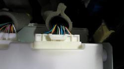
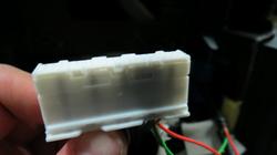
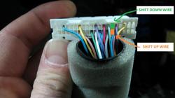
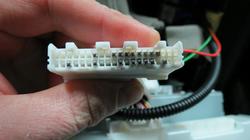
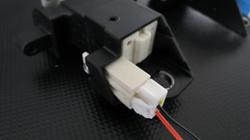
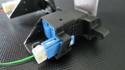
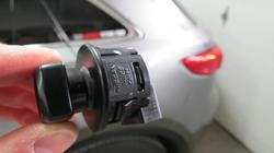
REX9271's Wire Harness - Shown below plugged into paddles (Green wire for left paddle, orange/red wire for right paddle):
HINT: Connectors are not interchangeable

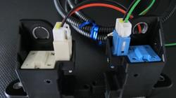
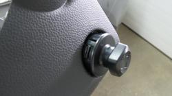
Close-up of the left paddle:

Close-up of the right paddle:

Steering Column Cover Set
- Required to install the paddles especially to push out the tilt switch to allow room for the left paddle
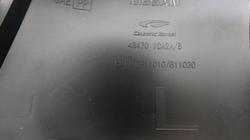
- Part number for BLACK is 48470-1CA2B
- Part number for BEIGE is 48470-1CA2A
- Original column cover is a two-piece whereas the paddle version is a four-piece
- Upper column cover of non-paddle version is identical to the paddle-version and can remain without having to swap it out. Discussed more later on in the DIY
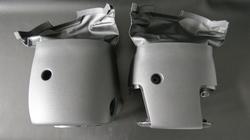
Photo showing the non-paddle 2-piece version for reference (Not the actual one you need, you already have this):

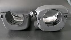
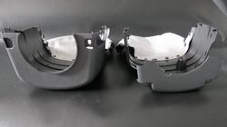
Photo showing the assembled paddle version 4-piece column cover set (The one you need):

Assembled paddle-version 4-piece column cover set - Front-View:

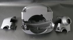
4-piece paddle version column cover set separated:

Photo showing part number of paddle-version column cover stamped on the inside for all you non-beliebers :rotfl: just kidding!

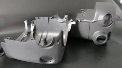
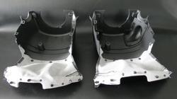
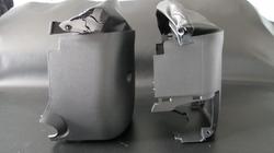
Comparison of the non-paddle version(left) and the paddle-version(right):
HINT: The top cover is identical between both versions but you can use the one already in your car.
Less hassle and no need to detach the clips holding the pleather
NOTE: For this photo comparison, the top piece from the left cover was not detached from the vehicle hence missing in the photo

Side-view(Left) Comparison of the non-paddle version(left) and the paddle-version(right):
NOTE: Notice the extended tilt switch opening in the cover on the right. This is to provide space for the left paddle switch

Side-view(Right) Comparison:

Bottom-view Comparison:

Front-view Comparison:
HINT: The paddle-version cover is missing the lip that goes inside the back of the steering wheel.
Intentional to allow the cover to fit once paddles have been mounted.

Rear-view Comparison:

Screw Covers:
HINT: The screw covers are the same between both column covers. Just re-use your own and save some cash:

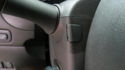
Tilt-Switch Location - 1/4:
NOTE: The paddle version has an extended tilt switch opening. Purposely to allow the left paddle and the tilt switch to co-exist in the same area.

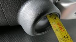
Tilt-Switch Location - 2/4:
NOTE: The photo below shows you the size of the tilt switch

Tilt-Switch Location - 3/4:
NOTE: The switch is pushed out 1 inch for those who might find this useful:

Tilt-Switch Location - 3/4:

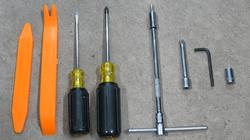
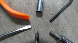
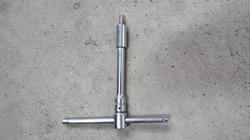
Step 3 - Tools
Tools Required (Shown from left to right):
- Trim removal tools
- Small flat screw driver
- Medium Philips screw driver
- 1/4" drive T-handle socket wrench
- 1/4" drive extension - long
- 1/4" drive extension - short
- 1/4" drive socket to 5/32 or 4mm hex bit
- 5/32 or 4mm allen key
- 1/4" drive 5/16 or 8mm socket


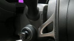
Step 4 - Getting Started
Position Your Vehicle: In a way you have ambient light and the ability to keep your driver-side door wide open
Removing Screw Covers & Philips Screws:
- For this you will require a flat and philips screwdriver.
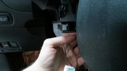
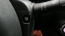
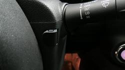
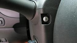
- Turn the steering wheel 90 degrees left exposing the screw cover:
Gently pry the screw cover off exposing the Philips screw underneath:
NOTE: Pry the cover from the side. Do not try to jamb it between the grooves in the face. That will leave a mark.

Turn the steering wheel back to center then 90 degrees right exposing the right screw cover:

Gently pry the screw cover off exposing the Philips screw underneath:
NOTE: Pry the cover from the side. Do not try to jamb it between the grooves in the face. That will leave a mark.

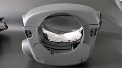
Next remove the Philips screw on the bottom of the lower steering column cover. You can feel your way to it:

Now you can separate the upper and lower halves of the column cover:
HINT: Pry the cover halves using a flat screw-driver wrapped in some fabric (ie., shirt) and place it between the turn-signal switch and upper cover
Repeat the same step with the other side and make sure to separate the upper and lower halves completely.
NOTE: Be careful not to break the little nipples on the lower cover located just left and right of the signal switch (seen in photo)

First push the upper and then the lower halves towards the dashboard to remove each cover's lip from the back of the steering wheel:
HINT:Use the tilt switch to extend the steering wheel away from the dashboard so you can do this step

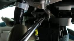
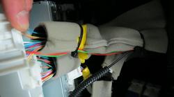
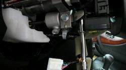
Now that you have the lower half detached, you will need to detach the harness leading into the tilt switch:
HINT: Just as any other connector, push the tab in and then push the connector out using the flat screwdriver.

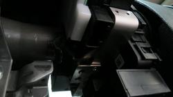
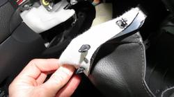
The lower column cover will have a pleather flap extending from the rear and clips into the lower dash cover:

Simply put your fingers over top the pleather flap(white fabric top side) and wrap your fingers underneath popping all the clips upward:
HINT: Once all clips have been popped, pull your hand out and remove the pleather flap with the lower column cover carefully

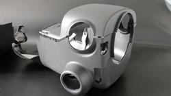
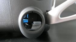
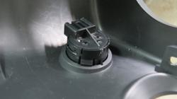
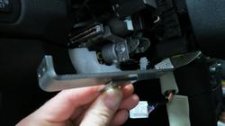
Now you need to remove the tilt switch from the old column cover:
HINT: There are tabs around the switch. Gently push them in and pop the switch out

Push the tilt switch out on a slight angle so its socket can come out:

This is what the tilt switch looks like removed:
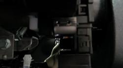
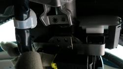
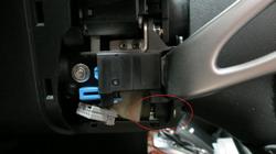
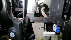
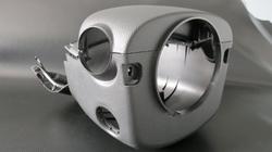
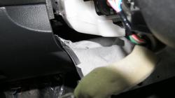
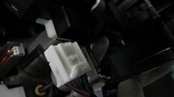
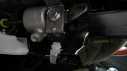
Remove the white connector located on the bottom-left to make room for fitting your bracket:

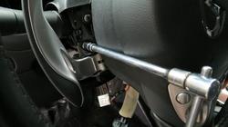
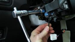
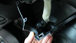
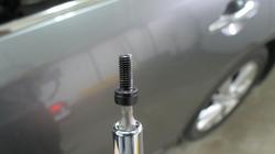
Using the hex bit (5/32 or 4mm) with a 1/4" extension and T-handle or choice of wrench, remove the two black hex bolts:


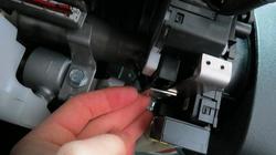
Temporarily connect the tilt switch and retract the bracket you just removed the bolts from:

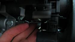
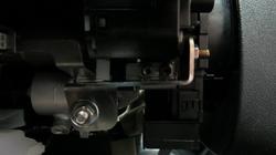
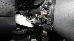
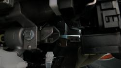
Carefully remove this white clip holding the cable. This will give you easier access to install the bracket:

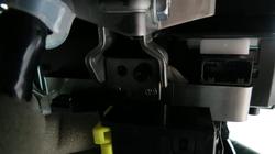
Take apart the bracket leaving the main piece and the centre mount as shown:
NOTE: The bracket will not install with the tight spaces surrounding its final location

....continued in next post
Available for the following Infiniti years and models:
EX / QX50 (2008 - 2014 model years)
FX / QX70 (2009 - 2014 model years)
IMPORTANT NOTES - READ FIRST!
NOTE 1: Steering column assembly must come with power tilt option.
NOTE 2: Verify your steering column requires this bracket before purchase. Some production runs do come with the mounting points already present on the steering column. See figure A & B for visual reference.
NOTE 3: Verify if the factory harness for the paddle shifters is present (See Fig C). Even with the factory mounting points, the wire harness may not be factory installed. Record shows 2009 year model has both.
NOTE 4: There has been production variations in the 2013 FX where some come with the factory mounting points while others come with a harness taped underneath the steering column. Verify your prior to ordering.
NOTE 5: Removing the steering wheel is not required and does not make the installation easier, just longer.
Step 1 - Verify bracket and wire harness requirements
Fig A - Showing OEM paddle mounts, no bracket necessary (Wire harness may be required):
Steering column view - Left
Steering Column View - Right
Fig B - Showing missing OEM paddle mounts and wire harness, REX9271's bracket and wire harness required:
Steering column view - Left
Steering column view - Right
Fig C - Showing factory harness taped up underneath steering column ready for an easy plug-n-play setup
Step 2 - Required Parts
REX9271's Paddle Shifter Mount/Harness Kit
- REX9271's paddle shifter mount and wiring harness kit can be found in the Vendor's section
( https://www.infinitiscene.com/searc...le-Shifter-bracket-kit-for-EX-amp-2Gen-FX-115 )
Infiniti Paddles
- You can use a pair of paddle shifters from either a Nissan 370Z, Infiniti G35, G37 with the Infiniti/Nissan part number of 25549-JK0000 (Black leather on the paddles)
- Other colors are available such as stone or beige if you wish to match your interior (May have varying names, consult local dealer for further details)
- A new set of black paddles at the dealer now goes for around $300 :eek.:
- Alternate colors such as beige or stoneare under $200. Some members have suggested plasti dipping/dying the leather though no reports of this being tested so far...
- You can also find a nice set of paddles on eBay for under $200 shipped
REX9271's Wire Harness - Shown below plugged into paddles (Green wire for left paddle, orange/red wire for right paddle):
HINT: Connectors are not interchangeable
Close-up of the left paddle:
Close-up of the right paddle:
Steering Column Cover Set
- Required to install the paddles especially to push out the tilt switch to allow room for the left paddle
- Part number for BLACK is 48470-1CA2B
- Part number for BEIGE is 48470-1CA2A
- Original column cover is a two-piece whereas the paddle version is a four-piece
- Upper column cover of non-paddle version is identical to the paddle-version and can remain without having to swap it out. Discussed more later on in the DIY
Photo showing the non-paddle 2-piece version for reference (Not the actual one you need, you already have this):
Photo showing the assembled paddle version 4-piece column cover set (The one you need):
Assembled paddle-version 4-piece column cover set - Front-View:
4-piece paddle version column cover set separated:
Photo showing part number of paddle-version column cover stamped on the inside for all you non-beliebers :rotfl: just kidding!
Comparison of the non-paddle version(left) and the paddle-version(right):
HINT: The top cover is identical between both versions but you can use the one already in your car.
Less hassle and no need to detach the clips holding the pleather
NOTE: For this photo comparison, the top piece from the left cover was not detached from the vehicle hence missing in the photo
Side-view(Left) Comparison of the non-paddle version(left) and the paddle-version(right):
NOTE: Notice the extended tilt switch opening in the cover on the right. This is to provide space for the left paddle switch
Side-view(Right) Comparison:
Bottom-view Comparison:
Front-view Comparison:
HINT: The paddle-version cover is missing the lip that goes inside the back of the steering wheel.
Intentional to allow the cover to fit once paddles have been mounted.
Rear-view Comparison:
Screw Covers:
HINT: The screw covers are the same between both column covers. Just re-use your own and save some cash:
Tilt-Switch Location - 1/4:
NOTE: The paddle version has an extended tilt switch opening. Purposely to allow the left paddle and the tilt switch to co-exist in the same area.
Tilt-Switch Location - 2/4:
NOTE: The photo below shows you the size of the tilt switch
Tilt-Switch Location - 3/4:
NOTE: The switch is pushed out 1 inch for those who might find this useful:
Tilt-Switch Location - 3/4:
Step 3 - Tools
Tools Required (Shown from left to right):
- Trim removal tools
- Small flat screw driver
- Medium Philips screw driver
- 1/4" drive T-handle socket wrench
- 1/4" drive extension - long
- 1/4" drive extension - short
- 1/4" drive socket to 5/32 or 4mm hex bit
- 5/32 or 4mm allen key
- 1/4" drive 5/16 or 8mm socket
Step 4 - Getting Started
Position Your Vehicle: In a way you have ambient light and the ability to keep your driver-side door wide open
Removing Screw Covers & Philips Screws:
- For this you will require a flat and philips screwdriver.
- Turn the steering wheel 90 degrees left exposing the screw cover:
Gently pry the screw cover off exposing the Philips screw underneath:
NOTE: Pry the cover from the side. Do not try to jamb it between the grooves in the face. That will leave a mark.
Turn the steering wheel back to center then 90 degrees right exposing the right screw cover:
Gently pry the screw cover off exposing the Philips screw underneath:
NOTE: Pry the cover from the side. Do not try to jamb it between the grooves in the face. That will leave a mark.
Next remove the Philips screw on the bottom of the lower steering column cover. You can feel your way to it:
Now you can separate the upper and lower halves of the column cover:
HINT: Pry the cover halves using a flat screw-driver wrapped in some fabric (ie., shirt) and place it between the turn-signal switch and upper cover
Repeat the same step with the other side and make sure to separate the upper and lower halves completely.
NOTE: Be careful not to break the little nipples on the lower cover located just left and right of the signal switch (seen in photo)
First push the upper and then the lower halves towards the dashboard to remove each cover's lip from the back of the steering wheel:
HINT:Use the tilt switch to extend the steering wheel away from the dashboard so you can do this step
Now that you have the lower half detached, you will need to detach the harness leading into the tilt switch:
HINT: Just as any other connector, push the tab in and then push the connector out using the flat screwdriver.
The lower column cover will have a pleather flap extending from the rear and clips into the lower dash cover:
Simply put your fingers over top the pleather flap(white fabric top side) and wrap your fingers underneath popping all the clips upward:
HINT: Once all clips have been popped, pull your hand out and remove the pleather flap with the lower column cover carefully
Now you need to remove the tilt switch from the old column cover:
HINT: There are tabs around the switch. Gently push them in and pop the switch out
Push the tilt switch out on a slight angle so its socket can come out:
This is what the tilt switch looks like removed:
Remove the white connector located on the bottom-left to make room for fitting your bracket:
Using the hex bit (5/32 or 4mm) with a 1/4" extension and T-handle or choice of wrench, remove the two black hex bolts:
Temporarily connect the tilt switch and retract the bracket you just removed the bolts from:
Carefully remove this white clip holding the cable. This will give you easier access to install the bracket:
Take apart the bracket leaving the main piece and the centre mount as shown:
NOTE: The bracket will not install with the tight spaces surrounding its final location
....continued in next post
Attachments
-
 paddleOEMboltPointsL.jpg46.5 KB · Views: 471
 -
 84344a21-9d92-4b5f-95f1-0690f5e0c7c9.jpg70.5 KB · Views: 477
 -
 2123593295_5eac4471be_o.jpg91 KB · Views: 444
 -
 46e6a4f8-fac8-490b-bcb7-82effadc8870.jpg90.1 KB · Views: 477
 -
 abdea976-8515-4818-921c-b1061bec885c.jpg102.6 KB · Views: 448
 -
 paddleOEMboltPointsR.jpg48 KB · Views: 477
 -
 IMG_1977.jpg29 KB · Views: 476
 -
 IMG_1979.jpg50.4 KB · Views: 445
 -
 IMG_1983.jpg45.7 KB · Views: 491
 -
 5fc2f341-7994-4cae-9748-3932a480445b.jpg54.5 KB · Views: 459
 -
 IMG_1990.jpg55.4 KB · Views: 460
 -
 IMG_1993.jpg53.1 KB · Views: 465
 -
 IMG_1994.jpg58.2 KB · Views: 456
 -
 IMG_1997.jpg52.5 KB · Views: 487
 -
 IMG_1991.jpg56.9 KB · Views: 444
 -
 IMG_1992.jpg60.5 KB · Views: 476
 -
 IMG_2000-1.jpg28.4 KB · Views: 441
 -
 IMG_2018.jpg70.4 KB · Views: 447
 -
 IMG_1999.jpg54.3 KB · Views: 437
 -
 IMG_1984.jpg56.1 KB · Views: 396
 -
 IMG_1988.jpg67.2 KB · Views: 453
 -
 IMG_1989.jpg57.1 KB · Views: 484
 -
 IMG_2198.jpg87.2 KB · Views: 448
 -
 IMG_2200.jpg94.7 KB · Views: 418
 -
 IMG_2129.jpg46.2 KB · Views: 393
 -
 IMG_2009.jpg63.1 KB · Views: 437
 -
 IMG_2037.jpg35 KB · Views: 473
 -
 IMG_2010.jpg60.8 KB · Views: 454
 -
 IMG_2025.jpg37.5 KB · Views: 419
 -
 IMG_2021.jpg49.5 KB · Views: 431
 -
 IMG_2020.jpg51.8 KB · Views: 414
 -
 IMG_2019.jpg70.3 KB · Views: 412
 -
 IMG_2018.jpg70.4 KB · Views: 429
 -
 IMG_2018.jpg70.4 KB · Views: 473
 -
 IMG_2034.jpg55.3 KB · Views: 453
 -
 IMG_2035.jpg30.3 KB · Views: 425
 -
 IMG_2033.jpg38 KB · Views: 429
 -
 IMG_2030.jpg44.2 KB · Views: 424
 -
 IMG_2029.jpg52.1 KB · Views: 424
 -
 IMG_2028.jpg57.4 KB · Views: 416
 -
 IMG_2044.jpg80.7 KB · Views: 428
 -
 IMG_2043.jpg30.9 KB · Views: 413
 -
 IMG_2037.jpg35 KB · Views: 429
 -
 IMG_2037.jpg35 KB · Views: 419
 -
 IMG_2036.jpg41 KB · Views: 369
 -
 IMG_2048.jpg34.3 KB · Views: 446
 -
 IMG_2051.jpg33.7 KB · Views: 435
 -
 IMG_2047.jpg25.8 KB · Views: 463
 -
 302.jpg75.2 KB · Views: 392
 -
 IMG_2046.jpg40.5 KB · Views: 468
 -
 IMG_2053.jpg42 KB · Views: 420
Last edited:


")